Archive
Busting Myths – IPv6 Link Local Next Hop into BGP
In some publications it is mentioned that a link local next-hop can’t be used when redistributing routes into BGP because routers receiving the route will not know what to do with the next-hop. That is one of the reason why HSRPv2 got support for global IPv6 addresses. One such scenario is described in this link.
The topology used for this post is the following.
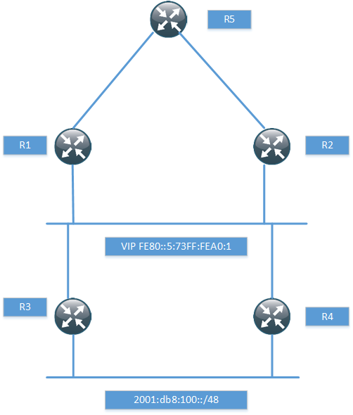
I have just setup enough of the topology to prove that it works with the next-hop, so I won’t be running any pings and so on. The routers R1 and R2 have a static route for the network behind R3 and R4.
ipv6 route 2001:DB8:100::/48 GigabitEthernet0/1 FE80::5:73FF:FEA0:1
When routing towards a link local address, the exit interface must be specified. R1 then runs BGP towards R5, notice that I’m not using next-hop-self.
router bgp 100
bgp router-id 1.1.1.1
bgp log-neighbor-changes
neighbor 2001:DB8:1::5 remote-as 100
!
address-family ipv6
redistribute static
neighbor 2001:DB8:1::5 activate
exit-address-family
If we look in the BGP RIB, we can see that the route is installed with a link local next-hop.
R1#sh bgp ipv6 uni
BGP table version is 2, local router ID is 1.1.1.1
Status codes: s suppressed, d damped, h history, * valid, > best, i - internal,
              r RIB-failure, S Stale, m multipath, b backup-path, f RT-Filter,
              x best-external, a additional-path, c RIB-compressed,
Origin codes: i - IGP, e - EGP, ? - incomplete
RPKI validation codes: V valid, I invalid, N Not found

     Network          Next Hop            Metric LocPrf Weight Path
 *>  2001:DB8:100::/48
                       FE80::5:73FF:FEA0:1
                                                0         32768 ?
What next-hop do we have at R5 though?
R5#sh bgp ipv6 uni
BGP table version is 10, local router ID is 5.5.5.5
Status codes: s suppressed, d damped, h history, * valid, > best, i - internal,
              r RIB-failure, S Stale, m multipath, b backup-path, f RT-Filter,
              x best-external, a additional-path, c RIB-compressed,
Origin codes: i - IGP, e - EGP, ? - incomplete
RPKI validation codes: V valid, I invalid, N Not found

     Network          Next Hop            Metric LocPrf Weight Path
 *>i 2001:DB8:100::/48
                       2001:DB8:1::1            0    100      0 ?
We see the next-hop of R1 and not the link local address. How did this happen? We aren’t using next-hop-self. If we debug at R1, we will see what happens.
R1#debug ip bgp updates
R1#debug ip bgp ipv6 uni
*Aug 30 06:19:15.863: BGP(1): 2001:DB8:1::5 NEXT_HOP part 1 net 2001:DB8:100::/48,
next FE80::5:73FF:FEA0:1
*Aug 30 06:19:15.863: BGP(1): Can't advertise 2001:DB8:100::/48 to 2001:DB8:1::5
with NEXT_HOP FE80::5:73FF:FEA0:1
*Aug 30 06:19:15.863: BGP(1): (base) 2001:DB8:1::5 send UPDATE (format)
2001:DB8:100::/48, next 2001:DB8:1::1, metric 0, path Local
We can see that BGP was going to advertise it with the link local next-hop but then realized that this would not work. It then replaced the link local next-hop with a global next-hop.
While it may have been true at some point that routes must point to a global next-hop, this does not hold true in modern code. BGP will automatically advertise its updates with a global next-hop.
IPv6 Multicast
These are my notes for IPv6 multicast for the CCDE exam. Overview
- Prefix FF::/8 reserved for multicast
- Multicast Listener Discovery (MLD) replaces IGMP
- MLD is part of ICMPv6
- MLDv1 equivalent to IGMPv2
- MLDv2 equivalent to IGMPv3
- ASM, SSM and Bidir supported
- PIM identified by IPv6 next header 103
- BSR and static RP supported
- No support for MSDP
- Anycast supported through PIM, defined in RFC4610
- Any Source Multicast (ASM)
- PIM-SM, PIM-BiDir
- Default for generic multicast and unicast prefix-based multicast
- Starts with FF3x::/12
- Source Specific Multicast (SSM)
- PIM-SSM
- FF3X::/32 is allocated for SSM by IANA
- Currently prefix and plen is zero so FF3X::/96 is useable for SSM
- Embedded RP groups
- PIM-SM, PIM-BIDir
- Starts with FF70::/12
IPv6 Multicast Addressing
IPv6 multicast address format includes variable bits to define what type of address it is and what the scope is of the multicast group. The scope can be:
1 – Node
2 – Link
3 – Subnet
4 – Admin
5 – Site
8 – Organization
E – Global
The flags define if embedded RP is used, if the address is based on unicast and if the address is IANA assigned or not (temporary). The unicast based IPv6 multicast address allows an organization to create globally unique IPv6 multicast groups based on their unicast prefixes. This is similar to GLOP addressing in IPv4 but does not require an Autonomous System Number (ASN). IPv6 also allows for embedding the RP address into the multicast address itself. This provides a static RP to multicast group mapping mechanism and can be used to provide interdomain IPv6 multicast as there is no MSDP in IPv6. When using Ethernet, the destination MAC address of the frame will start with 33:33 and the remaining 32 bits will consist of the low order 32 bits of the IPv6 multicast address.
Well Known Multicast Addresses
FF02::1 – All Nodes
FF02::2 – All Routers
FF02::5 – OSPF All Routers
FF02::6 – OSPF DR Routers
FF02::A – EIGRP Routers
FF02::D – PIM Routers
Neighbor Solicitation and DAD
IPv6 also uses multicast to replace ARP through the neighbor solicitation process. To do this the solicited node multicast address is used and the prefix is FF02::1:FF/104 and the last 24 bits are taken from the lower 24 bits of the IPv6 unicast address. If Host A needs to get the MAC of Host B, Host A will send the NS to the solicited node multicast address of B. IPv6 also does Duplicate Address Detection (DAD) to check that noone else is using the same IPv6 address and this also uses the solicited node multicast address. If Host A is checking uniqueness of its IPv6 address, the message will be sent to the solicited node multicast address of Host A.
Multicast Listener Discovery (MLD)
- MLDv1 messages
- Listener Query
- Listener Report
- Listener Done
- MLDv2 messages
- Listener Query
- Listener Report
MLDv2 does not use a specific Done message which is equivalent to the Leave message in IGMP. It will stop sending Reports or send a Report which excludes the source it was previously interested in.
Protocol Independent Multicast (PIM) for IPv6
- PIM-SM (RP is required)
- Many to many applications (multiple sources, single group)
- Uses shared tree initially but may switch to source tree
- PIM-BiDir (RP is required)
- Bidirectional many to many applications (hosts can be sources and receivers)
- Only uses shared tree, less state
- PIM-SSM
- One to many applications (single source, single group)
- Always uses source tree
- Source must be learnt through out of band mechanism
Anycast RP
IPv6 does not have support for MSDP. It can support anycast RP through the use of PIM which can implement this feature. All the RPs doing anycast will use the same IPv6 address but they also require a unique IPv6 address that will be used to relay the PIM Register messages coming from the multicast sources. A RP-set is defined with the RPs that should be included in the Anycast RP and the PIM Register messages will be relayed to all the RPs defined in the RP-set. If the PIM Register message comes from an IPv6 address that is defined in the RP-set, the Register will not be sent along which is a form of split horizon to prevent looping of control plane messages. When a RP relays a PIM Register, this is done from a unique IPv6 address which is similar to how MSDP works.
Sources will find the RP based on the unicast metric as is normally done when implementing anycast RP. If a RP goes offline, messages will be routed to the next RP which now has the best metric.
Interdomain Multicast
These are my thoughts on interdomain multicast since there is no MSDP for IPv6. Embedded RP can be used which means that other organization needs to use your RP. Define a RP prefix that is used for interdomain multicast only or use a prefix that is used for internal usage but implement a data plane filter to filter out requests for groups that should not cross organizational boundaries. This could also be done by filtering on the the scope of the multicast address.
Another option would be to anycast RP with the other organization but this could get a lot messier unless a RP is defined for only a set of groups that are used for interdomain multicast. Each side would then have a RP defined for the groups and PIM Register messages would be relayed. The drawback would be that both sides could have sources but the policy may be that only one side should have sources and the other side only has listeners. This would be difficult to implement in a data plane filter. It might be possible to solve in the control plane by defining which sources the RP will allow to Register.
If using SSM, there is no need for a RP which makes it easier to implement interdomain multicast. There is always the consideration of joining two PIM domains but this could be solved by using static joins at the edge and implementing data plane filtering. Interdomain multicast is not something that is implemented a lot and it requires some thought to not merge into one failure domain and one administrative domain.
Final Thoughts
Multicast is used a lot in IPv6, multicast is more tightly integrated into the protocol than in IPv4, and it’s there even if you see it or not. The addressing, flags and scope can be a bit confusing at first but it allows for using multicast in a better way in IPv6 than in IPv4.
Service Provider IPv6 Deployment
These are my study notes regarding IPv6 deployment in SP networks in preparation for the CCDE exam.
Drivers for implementing IPv6
- External drivers
- SP customers that need access to IPv6 resources
- SP customers that need to interconnect their IPv6 sites
- SP customers that need to interface with their own customers over iPv6
- Internal drivers
- Handle problems that may be hard to fix with IPv4 such as large number of devices (cell phones, IP cameras, sensors etc)
- Public IPv4 address exhaustion
- Private IPv4 address exhaustion
- Strategic drivers
- Long term expansion plans and service offerings
- Preparing for new services and gaining competitive advantage
Infrastructure
- SP Core Infrastructure
- Native IPv4 core
- L2TPv3 for VPNs
- MPLS core
- MPLS VPNs
My reflection is that most cores would be MPLS enabled, however there are projects such as Terastream in Deutsche Telekom where the entire core is IPv6 enabled and L2TPv3 is used in place of MPLS.
- IPv6 in Native IPv4 Environments
- Tunnel v6 in v4
- Native v6 with dedicated resources
- Dual stack
The easiest way to get going with v6 was to tunnel it over v4. The next logical step was to enable v6 but on separate interfaces to not disturb the “real” traffic and to be able to experiment with the protocol. The end goal is dual stack, at least in a non MPLS enabled network.
- IPv6 in MPLS environments
- 6PE
- 6VPE
6PE is a technology to run IPv6 over an IPv4 enabled MPLS network. 6VPE does the same but with VRFs.
- Native IPv6 over Dedicated Data Link
- Dedicated data links between core routers
- Dedicated data links to IPv6 customers
- Connection to an IPv6 IX
- Dual stack
- All P + PE routers capable of v4 + v6 transport
- Either two IGPs or one IGP for both v4 + v6
- Requires more memory due to two routing tables
- IPv6 multicast natively supported
- All IPv6 traffic is routed in global space (no MPLS)
- Good for content distribution and global services (Internet)
- 6PE
- IPv6 global connectivity over an IPv4 MPLS core
- Transition mechanism (debatable)
- PEs are dual stacked and need 6PE configuration
- IPv6 reachability exchanged via MPBGP over iBGP sessions
- IPv6 packets transported from 6PE to 6PE inside MPLS
- The next-hop is an IPv4 mapped IPv6 address such as ::FFFF:1.1.1.1
- BGP label assigned for the IPv6 prefix
- Bottom label used due to P routers not v6 capable and for load sharing
- neighbor send-label is configured under BGP address-family ipv6
6PE is viewed as a transition mechanism but this is arguable, if you transport IPv4 over MPLS, you may want to do the same with IPv6 as well for consistency. Running 6PE means that there is fate sharing between v4 and v6 though, which could mean that an outage may affect both protocols. This could be avoided by running MPLS for IPv4 but v6 natively.
- Core network (P routers) left untouched
- IPv6 traffic inherits MPLS benefits such as fast-reroute and TE
- Incremental deployment possible (upgrade PE routers first)
- Each site can be v4-only, v4-VPN-only, v4+v6, v4-VPN+v6 and so on
- Scalability concerns due to separate RIB and FIB required per customer
- Mostly suitable for SPs with limited amount of PEs
- 6vPE
- Equivalent of VPNv4 but for IPv6
- Add VPNv6 address family under MPBGP
- Send extended communities for the prefixes under the address family
It is a common misconception for 6PE and 6vPE that traceroutes are not possible, that is however not entirely true. A P router can generate ICMPv6 messages that will follow the LSP to the egress PE and then the ICMPv6 error message is forwarded back to the originator of the traceroute.
- Route reflectors for 6PE and 6vPE
- Needed to scale BGP full mesh
- Dedicated RRs or data path RRs
- Either dedicated RR per AF or have multiple AFs per RR
- 6PE-RR must support IPv6 + label functionality
- 6vPE-RR must support IPv6 + label and extended communities functionality
PA vs PI
- PA advantages
- Aggregation towards upstreams
- Minimizes Internet routing table size
- PA disadvantages
- Customer is “locked” with the SP
- Renumbering can be painful
- Multi-homing and TE problems
The main driver here is if you are going to multi home or not. Renumbering is always painful but at least less so on IPv6 due to being able to advertise multiple IPv6 prefixes through Router Advertisements (RA).
- PI advantages
- Customers are not “locked” to the SP
- Multi homing is straight forward
- PI disadvantages
- Larger Internet routing table due to lack of efficient aggregation
- Memory and CPU needs on BGP speakers
Infrastructure Addressing (LLA vs global)
What type of addresses should be deployed on infrastructure links?
- Link Local Address FE80::/10
- Non routeable address
- Less attack surface
- Smaller routing tables
- Can converge faster due to smaller RIB/FIB
- Less need for iACL at edge of network
- Can’t ping links
- Can’t traceroute links
- May be more complex to manage with NMS
- Use global address on loopback for ICMPv6 messages
- Will not work with RSVP-TE tunnels
- Global only 2000::/3 (current IANA prefix)
- Globally routeable
- Larger attack surface unless prefix suppression is used
- Use uRPF and iACL at edge to protect your links
- Easier to manage
It would be interesting to hear if you have seen any deployments with LLA only on infrastructure links. In theory it’s a nice idea but it may corner you in some cases, preventing you from implementing other features that you wish to deploy in your network.
Use /126 or /127 on P2P links which is the equivalent of /30 or /31 on IPv4 links. For loopbacks use /128 prefixes. Always assign addresses from a range so that creating ACLs and iACLs becomes less tedious.
Using another prefix than /64 on an interface will break the following features:
- Neighbor Discovery (ND)
- Secure Neighbor Discovery (SEND)
- Privacy extensions
- PIM-SM with embedded RP
This is of course for segments where there are end users.
Prefix Allocation Practices
- Many SPs offer /48, /52, /56, /60 or /64 prefixes
- Enterprise customers receive one /48 or more
- Small business customers receive /52 or /56 prefix
- Broadband customers may receive /56 or /60 via DHCP Prefix Delegation (DHCP-PD)
Debating prefix allocation prefixes is like debating religion, politics or your favourite OS. Whatever you choose, make sure that you can revise your practice as future services and needs arrise.
Carrier Grade NAT(CGN)
- Short term solution to IPv4 exhaustage without changing Residential Gateway (RG) or SP infrastructure
- Subscriber uses NAT44 and SP does CGN with NAT44
- Multiplexes several customers onto the same public IPv4 address
- CGN performance and capabilities should be analysed in the planning phase
- May provide challenges in logging sessions
- Long term solution is to deploy IPv6
I really don’t like CGN, it slows down the deployment of IPv6. It’s a tool like anything else though that may be used selectively if there is no other solution available.
IPv6 over L2TP Softwires
- Dual stack IPv4/IPv6 on RG LAN side
- PPPoE or IPv4oE terminated on v4-only BNG
- L2TPv2 softwire between RG and IPv6-dedicated L2TP Network Server (LNS)
- Stateful architecture on LNS
- Offers dynamic control and granular accounting of IPv6 traffic
- Limited investment needed and limited impact on existing infrastructure
I have never seen IPv6 deployed over softwires, what about you readers?
6RD
- Uses 6RD CE (Customer Edge) and 6RD BR (Border Relay)
- Automatic prefix delegation on 6RD CE
- Stateless and automatic IPv6 in IPv4 encap and decap functions on 6RD
- Follows IPv4 routing
- 6RD BRs are adressed with IPv4 anycast for load sharing and resiliency
- Limited investment and impact on existing infrastructure
IPv4 via IPv6 Using DS-Lite with NAT44
- Network has migrated to IPv6 but needs to provide IPv4 services
- IPv4 packets are tunneled over IPv6
- Introduces two components: B4 (Basic Bridging Broadband Element) and AFTR (Address Family Transition Router)
- B4 typically sits in the RG
- AFTR is located in the core infrastructure
- Does not provide IPv4 and IPv6 hosts to talk to each other
- AFTR device terminates the tunnel and decapsulates IPv4 packet
- AFTR device performs NAT44 on customer private IP to public IP addresses
- Increased MTU, be aware of fragmentation
Connecting IPv6-only with IPv4-only (AFT64)
- Only applicable where IPv6-only hosts need to communicate with IPv4-only hosts
- Stateful or stateless v6 to v4 translation
- Includes NAT64 and DNS64
MAP (Mapping of Address and Port)
- MAP-T Stateless 464 translation
- MAP-E Stateless 464 encapsulation
- Allows sharing of IPv4 address across an IPv6 network
- Each shared IPv4 endpoint gets a unique TCP/UDP port range via “rules”
- All or part of the IPv4 address can be derived from the IPv6 prefix
- This allows for route summarization
- Need to allocate TCP/UDP port ranges to each CPE
- Stateless border relays in SP network
- Can be implemented in hardware for superior performance
- Can use anycast and have asymmetric routing
- No single point of failure
- Leverages IPv6 in the network
- No CGN inside SP network
- No need for logging or ALGs
- Dependent on CPE router
NAT64
- Stateful or stateless translation
- Stateful
- 1:N translation
- “PAT”
- TCP, UDP, ICMP
- Shares IPv4 addresses
- Stateless
- 1:1 translation
- “NAT”
- Any protocol
- No IPv4 address savings
DNS64 is often required in combination with NAT64 to send AAAA response to the IPv6-only hosts in case the server only exists in the v4 world.
464XLAT
- Somewhere around 15% of apps break with native v6 or NAT64
- Skype is one of these apps
- 464XLAT can help with most of these applications
- Handset does stateless 4 to 6 translation
- Network does NAT64
- Deployed by T-Mobile
A Quick Look at NAT64 and NAT46
Introduction
In the best of worlds we would all be using native IPv6 now, or at least dual
stack. That is not the case however and IPv4 will be around for a long time yet.
During that time that both protocols exist, there will be a need to translate
between the two, like it or not.
Different Types of NAT
Before we begin, let’s define some different forms of NAT:
NAT44 – NAT from IPv4 to IPv4
NAT66 – NAT from IPv6 to IPv6
NAT46 – NAT from IPv4 to IPv6
NAT64 – NAT from IPv6 to IPv4
The most commonly used type is definitely NAT44 but here we will focus on translating
between IPv4 and IPv6.
NAT64
There are two different forms of NAT64, stateless and statefull. The stateless version
maps the IPv4 address into an IPv6 prefix. As the name implies, it keeps no state.
It does not save any IP addresses since every v4 address maps to one v6 address.
Here is a comparison of stateless and statefull NAT64:

DNS64
When resolving names to numbers in IPv4, A records are used. When doing the same
in IPv6, AAAA records are used. When using NAT64, the device doing the translation
will translate between A and AAAA records. The function of DNS64 will not be
described further in this post.
Documentation
The configuration guides at Cisco.com are pretty poorly written and there is
not much else to find on configuring NAT64 on ASA. That’s always one of my goals
with a blog post, to learn a topic and to help spread knowledge into the networking
community.
The Lab
To demonstrate NAT64, the following topology is used:

The goal is for IOS9 to source traffic from its loopback 2001:db8:0:9::9 to
IOS7 with the IP address 203.0.113.2. The routers have some basic configuration
with IP addresses on the interfaces and static routing.
IOS7:
interface GigabitEthernet0/0
 ip address 203.0.113.2 255.255.255.248
!
ip route 0.0.0.0 0.0.0.0 203.0.113.1
IOS8:
ipv6 unicast-routing
!
interface GigabitEthernet0/0
 ipv6 address 2001:DB8::2/64
!
interface GigabitEthernet0/1
 ipv6 address 2001:DB8:0:1::2/64
!
ipv6 route 2001:DB8:0:9::9/128 2001:DB8:0:1::1
ipv6 route ::/0 2001:DB8::1
IOS9:
ipv6 unicast-routing
interface Loopback0
 ipv6 address 2001:DB8:0:9::9/64
!
interface GigabitEthernet0/0
 ipv6 address 2001:DB8:0:1::1/64
!
ipv6 route ::/0 2001:DB8:0:1::2
The ASA is the device that will be doing the NAT64. It has one IPv4 interface and
one IPv6 interface. It starts with the following configuration:
ASA1:
interface GigabitEthernet0/0
 nameif inside
 security-level 100
 ip address 203.0.113.1 255.255.255.248
!
interface GigabitEthernet0/1
 nameif outside
 security-level 0
 no ip address
 ipv6 address 2001:db8::1/64
!
access-list outside extended permit icmp6 any any
!
ipv6 route outside 2001:db8:0:9::9/128 2001:db8::2
In newer versions of ASA code, unified ACL is supported. That means we can have
both IPv4 and IPv6 in the same ACL. In my ACL I am allowing ICMPv6 to come in
on the “outside” interface.
To translate between IPv6 and IPv4, NAT must be configured. Both object NAT and
twice NAT is supported but I prefer twice NAT, so that is what I will configure.
When pinging from IOS9, we need to define an address that will represent IOS7 (IPv6).
This is the destination of the packet. The source address of IOS9 needs to be translated
to an IPv4 address as well. This picture will show the flow of the traffic:

Time to configure the ASA. The traffic flow is coming in on the interface “outside”
and exiting on interface “inside”. We need to define network objects, try to name
them properly because otherwise it can be confusing to understand the traffic flow.
object network REALv6_OUTSIDE
host 2001:db8:0:9::9
object network MAPPED_IPv4_INSIDE
host 192.0.2.1
object network MAPPED_IPv6_OUTSIDE
host 2001:db8:0:a::2
object network REALv4_INSIDE
host 203.0.113.2
nat (outside,inside) source static REALv6_OUTSIDE MAPPED_IPv4_INSIDE destination
static MAPPED_IPv6_OUTSIDE REALv4_INSIDE net-to-net
The syntax can be a bit confusing so let’s take a closer look:
REALv6_OUTSIDE – This is the source IP(v6) of IOS9
MAPPED_IPv4_INSIDE – This is what IOS9 gets translated to on the inside
MAPPED_IPv6_OUTSIDE – This is the destination IOS9 is sending traffic to
REALv4_INSIDE – This is what the destination gets translated to on the inside
To test our setup, we will ping from IOS9:
IOS9#ping 2001:DB8:0:A::2 so lo0
Type escape sequence to abort.
Sending 5, 100-byte ICMP Echos to 2001:DB8:0:A::2, timeout is 2 seconds:
Packet sent with a source address of 2001:DB8:0:9::9
!!!!!
Success rate is 100 percent (5/5), round-trip min/avg/max = 1/5/11 ms
IOS7#debug ip icmp
ICMP packet debugging is on
IOS7#
*Aug 26 07:28:27.786: ICMP: echo reply sent, src 203.0.113.2, dst 192.0.2.1, topology BASE, dscp 0 topoid 0
*Aug 26 07:28:27.796: ICMP: echo reply sent, src 203.0.113.2, dst 192.0.2.1, topology BASE, dscp 0 topoid 0
*Aug 26 07:28:27.802: ICMP: echo reply sent, src 203.0.113.2, dst 192.0.2.1, topology BASE, dscp 0 topoid 0
*Aug 26 07:28:27.810: ICMP: echo reply sent, src 203.0.113.2, dst 192.0.2.1, topology BASE, dscp 0 topoid 0
*Aug 26 07:28:27.811: ICMP: echo reply sent, src 203.0.113.2, dst 192.0.2.1, topology BASE, dscp 0 topoid 0
That worked! Let’s take a look at the XLATE table:
ASA1#  show xlate
2 in use, 2 most used
Flags: D - DNS, e - extended, I - identity, i - dynamic, r - portmap,
       s - static, T - twice, N - net-to-net
NAT from outside:2001:db8:0:9::9/128 to inside:192.0.2.1
    flags sTN idle 0:01:04 timeout 0:00:00
NAT from inside:203.0.113.2 to outside:2001:db8:0:a::2/128
    flags sTN idle 0:01:04 timeout 0:00:00
That was ICMP. How about TCP? We need to allow TCP through the firewall.
ASA1(config)# access-list outside permit tcp any any
IOS7(config)#username nat password nat
IOS7(config)#line vty 0 4
IOS7(config-line)#login local
IOS9#telnet 2001:DB8:0:A::2 /source-interface lo0
Trying 2001:DB8:0:A::2 ... Open

User Access Verification

Username:
No matter what you think of NAT, that is pretty cool!
ASA1# show conn
1 in use, 4 most used

TCP outside  192.0.2.1(2001:db8:0:9::9):16809 inside  203.0.113.2:23, idle 0:00:43, bytes 2805, flags UIOB

ASA1# show nat det
Manual NAT Policies (Section 1)
1 (outside) to (inside) source static REALv6_OUTSIDE MAPPED_IPv4_INSIDE   destination static MAPPED_IPv6_OUTSIDE REALv4_INSIDE net-to-net
    translate_hits = 6, untranslate_hits = 24
    Source - Origin: 2001:db8:0:9::9/128, Translated: 192.0.2.1/32
    Destination - Origin: 2001:db8:0:a::2/128, Translated: 203.0.113.2/32
This was NAT64 in action. With our NAT we were doing one to one translation
between IPv6 and IPv4. If IPv4 addresses are scarce, we can define a NAT
pool and translate to that.
ASA1(config)# object network IPv4_POOL
ASA1(config-network-object)# range 198.51.100.1 198.51.100.5
ASA1(config-network-object)# exit
ASA1(config)# nat (outside,inside) source dynamic REALv6_OUTSIDE pat-pool IPv4_POOL
destination static MAPPED_IPv6_OUTSIDE REALv4_INSIDE net-to-net
IOS9#telnet 2001:db8:0:a::2 /source-interface lo0
Trying 2001:DB8:0:A::2 ... Open

User Access Verification

Username:
ASA1# show xlate
2 in use, 3 most used
Flags: D - DNS, e - extended, I - identity, i - dynamic, r - portmap,
       s - static, T - twice, N - net-to-net
NAT from inside:203.0.113.2 to outside:2001:db8:0:a::2/128
    flags sTN idle 0:00:42 timeout 0:00:00

TCP PAT from outside:2001:db8:0:9::9/43376 to inside:198.51.100.1/43376 flags ri idle 0:00:42 timeout 0:00:30
ASA1# show nat detail
Manual NAT Policies (Section 1)
1 (outside) to (inside) source dynamic REALv6_OUTSIDE pat-pool IPv4_POOL  destination static MAPPED_IPv6_OUTSIDE REALv4_INSIDE net-to-net
    translate_hits = 9, untranslate_hits = 10
    Source - Origin: 2001:db8:0:9::9/128, Translated (PAT): 198.51.100.1-198.51.100.5
    Destination - Origin: 2001:db8:0:a::2/128, Translated: 203.0.113.2/32

ASA1# show conn
1 in use, 4 most used

TCP outside  198.51.100.1(2001:db8:0:9::9):20135 inside  203.0.113.2:23, idle 0:00:01, bytes 1382, flags UIOB
The source got translated to 198.51.100.1 through PAT.
Conclusion
IPv6 is here to stay, but so is also IPv4 for a long time to come. Personal
opinions aside, we may need to translate between IPv6 and IPv4 for a time to
come. Knowing how to configure NAT64 is just another tool in our belt.
IPv6 operation and best practices – documents to read
Unfortunately I don’t get to do much v6 at my job yet but I still like to stay updated on
what is happening. Do you run any v6 in your network? If so, do you run it native or tunneled
or something like 6PE?
Here are some interesting sources for operation of v6.
draft-matthews-v6ops-design-guidelines-01
This document discusses if IPv4 and IPv6 traffic
should be mixed on the same interface or should different interfaces be used? Should
link local or global addressing be used for routing? Should v6 routes be transferred
over v4 in BGP sessions?
draft-ietf-v6ops-enterprise-incremental-ipv6-01
This document is for deploying v6 in an enterprise network. Things like security policy,
addressing plan and IPv6 myths are brought up.
This document is purely about the advantages and disadvantages of only running link local
addresses.
Also, don’t miss out on information that is freely available at Cisco Live. Here are
some interesting sessions on IPv6 from Melbourne.
BRKRST-2301 – Enterprise IPv6 Deployment (2013 Melbourne)
BRKRST-1069 – Understanding IPv6 (2013 Melbourne)
ITMGEN-1313 – Preparing for IPv6 in the Enterprise (2013 Melbourne)
BRKRST-2311 – IPv6 Planning, Deployment and Troubleshooting (2013 Melbourne)
BRKSEC-2003 – IPv6 Security Threats and Mitigations (2013 Melbourne)
COCRST-2464 – Inside Cisco IT: Making The Leap To IPv6 (2013 Melbourne)
As you can see. IPv6 is a pretty big deal these days at Cisco Live. Then you also have
books, configuration guides etc but this should give you a good start to see what challenges
and considerations you should have when deploying IPv6.
Frame-relay IPv6 speed drill
Going for the lab we need both speed and skills. I made a simple IPv6 frame-relay lab that should test your speed. Time yourself and post your time to configure in the comments. Just by looking at the time I could probably tell if you are typing manually or not. This is the scenario.
Routers R1, R2, R3 and R4 are connected to a frame-relay cloud. They are all spokes connecting to the hub R5. R1 has a DLCI 105 to R5 which is 501 from R5 POV. R2 has a DLCI that is 205 and 502 from R5 POV and so on. This is the task.
Configure all devices with a global address of 2001:1:0:1234::Y where Y is the device number.
Configure static mappings on all devices.
All devices should be able to ping each other.
Download the .net from here and then edit for your IOS version and working dir etc.
I didn’t time myself but I think I could do it in less than 2 minutes for sure. Later I will post some tips on how to improve speed.
IPv6 over frame relay
This post will look at IPv6 over frame-relay and describe some of the small things
that differ compared to IPv4 and some gotchas.
We start out with the same topology as in my previous frame-relay post.

We configure routers R1, R2 and R3 to be in the subnet 2001:CC1E:1:1::/64.
Remember that the pool of global IPv6 unicast addresses comes from 2000::/3
which means that all today legit IPv6 addresses will start with a 2 or a 3.
R1
interface Serial0/0
encapsulation frame-relay
ipv6 address 2001:CC1E:1:1::1/64
frame-relay map ipv6 2001:CC1E:1:1::2 102
frame-relay map ipv6 2001:CC1E:1:1::3 103
I won’t say much about this config as this should be known to you if you read
my previous post on frame relay. We are using a physical interface so all DLCI’s
will be available to us. The first thing to notice about IPv6 over frame relay is that
there is no inverse ARP. This means that we need static mappings or the
frame-relay interface-dlci command on point-to-point interfaces.
We configure R2 and to mix things up a bit we use a point-to-point interface.
interface Serial0/0
encapsulation frame-relay
frame-relay interface-dlci 201
Since this is a point-to-point interface there is no need for static mappings.
R3 will use a multipoint interface but not the physical interface. We will use a
static mapping.
interface Serial0/0
encapsulation frame-relay
interface Serial0/0.301 multipoint
ipv6 add 2001:CC1E:1:1::3/64
frame-relay map ipv6 2001:CC1E:1:1::1 301
When we use IPv6 we always have a link-local address assigned to all IPv6 enbabled
interfaces. This can be seen with the show ipv6 interface brief command.
R1#sh ipv6 int brief
FastEthernet0/0 [administratively down/down]
Serial0/0 [up/up]
FE80::C001:8FF:FEE0:0
2001:CC1E:1:1::1
The link-local address is calculated based on the MAC address.
R1#sh int | i bia
Hardware is Gt96k FE, address is c201.08e0.0000 (bia c201.08e0.0000)
Hardware is Gt96k FE, address is c201.08e0.0001 (bia c201.08e0.0001)
Our link-local address is based on the first MAC of this output. We want to use
an easier to remember address so we set the link local address to FE80::1 and
then the same on R2 and R3 but with ::2 and ::3.
R1(config)#int s0/0
R1(config-if)#ipv6 add FE80::1 link-local
Now it is time to do some routing. We start out with BGP. Knowing BGP is of
course a must when you are studying for the CCIE and the difference between
IPv4 and IPv6 is not that great. We need networks to announce so we create
some loopbacks on the routers.
R1
R1(config-if)#int lo0
R1(config-if)#ipv6 add 2001:CC1E:10:1::1/64
R2
R1(config-if)#int lo0
R1(config-if)#ipv6 add 2001:CC1E:11:1::2/64
R3
R1(config-if)#int lo0
R1(config-if)#ipv6 add 2001:CC1E:12:1::3/64
Don’t you just love being able to have IP addresses with CCIE in them? 😉
Time to setup BGP. We will be using AS 100 for R1 and R2. R3 will be in AS 300.
R1
R1(config)#ipv6 unicast-routing
R1(config)#router bgp 100
R1(config-router)#nei 2001:CC1E:1:1::2 remote-as 100
R1(config-router)#address-family ipv6 unicast
R1(config-router-af)#neighbor 2001:CC1E:1:1::2 activate
R1(config-router-af)#network 2001:CC1E:10:1::/64
R1(config-router-af)#exit
R1(config-router)#bgp router-id 1.1.1.1
Notice that we need to set a router-ID because we have no IPv6 addresses
configured on the routers.
R2
R2(config)#ipv6 unicast-routing
R2(config)#router bgp 100
R2(config-router)#bgp router-id 2.2.2.2
R2(config-router)#nei 2001:CC1E:1:1::1 remote-as 100
R2(config-router)#address-family ipv6 unicast
R2(config-router-af)#nei 2001:CC1E:1:1::1 activate
R2(config-router-af)#network 2001:CC1E:11:1::/64
The session comes up and we receive one prefix.
*Mar 1 10:12:46.853: %BGP-5-ADJCHANGE: neighbor 2001:CC1E:1:1::2 Up
R1#sh bgp ipv6 uni sum
BGP router identifier 1.1.1.1, local AS number 100
BGP table version is 3, main routing table version 3
2 network entries using 304 bytes of memory
2 path entries using 152 bytes of memory
3/2 BGP path/bestpath attribute entries using 372 bytes of memory
0 BGP route-map cache entries using 0 bytes of memory
0 BGP filter-list cache entries using 0 bytes of memory
Bitfield cache entries: current 1 (at peak 1) using 32 bytes of memory
BGP using 860 total bytes of memory
BGP activity 3/1 prefixes, 3/1 paths, scan interval 60 secs
Neighbor V AS MsgRcvd MsgSent TblVer InQ OutQ Up/Down State/PfxRcd
2001:CC1E:1:1::2
4 100 8 8 3 0 0 00:04:03 1
Lets see if we have reachability.
R1#sh ipv6 route 2001:CC1E:11:1::/64
IPv6 Routing Table – 6 entries
Codes: C – Connected, L – Local, S – Static, R – RIP, B – BGP
U – Per-user Static route, M – MIPv6
I1 – ISIS L1, I2 – ISIS L2, IA – ISIS interarea, IS – ISIS summary
O – OSPF intra, OI – OSPF inter, OE1 – OSPF ext 1, OE2 – OSPF ext 2
ON1 – OSPF NSSA ext 1, ON2 – OSPF NSSA ext 2
D – EIGRP, EX – EIGRP external
B 2001:CC1E:11:1::/64 [200/0]
via 2001:CC1E:1:1::2
R1#ping 2001:CC1E:11:1::2
Type escape sequence to abort.
Sending 5, 100-byte ICMP Echos to 2001:CC1E:11:1::2, timeout is 2 seconds:
!!!!!
Indeed we do, now lets setup peering between R1 and R3.
R1
R1(config-router)#nei 2001:CC1E:1:1::3 remote-as 300
R1(config-router)#address-family ipv6 unicast
R1(config-router-af)#nei 2001:CC1E:1:1::3 activate
R3
R3(config-router)#nei 2001:CC1E:1:1::1 remote-as 100
R3(config-router)#address-family ipv6 unicast
R3(config-router-af)#nei 2001:CC1E:1:1::1 activate
Now lets look at the BGP table on R1.
R1#sh bgp ipv6 uni
BGP table version is 12, local router ID is 1.1.1.1
Status codes: s suppressed, d damped, h history, * valid, > best, i – internal,
r RIB-failure, S Stale
Origin codes: i – IGP, e – EGP, ? – incomplete
Network Next Hop Metric LocPrf Weight Path
*> 2001:CC1E:10:1::/64
:: 0 32768 i
*>i2001:CC1E:11:1::/64
2001:CC1E:1:1::2
0 100 0 i
*> 2001:CC1E:12:1::/64
2001:CC1E:1:1::3
0 0 300 i
We can see R3’s loopback, nothing weird, yet…We have a next-hop of
2001:CC1E:1:1::3 which is expected. Now look at the show ipv6 route bgp
output.
R1#sh ipv6 route bgp
IPv6 Routing Table – 7 entries
Codes: C – Connected, L – Local, S – Static, R – RIP, B – BGP
U – Per-user Static route, M – MIPv6
I1 – ISIS L1, I2 – ISIS L2, IA – ISIS interarea, IS – ISIS summary
O – OSPF intra, OI – OSPF inter, OE1 – OSPF ext 1, OE2 – OSPF ext 2
ON1 – OSPF NSSA ext 1, ON2 – OSPF NSSA ext 2
D – EIGRP, EX – EIGRP external
B 2001:CC1E:11:1::/64 [200/0]
via 2001:CC1E:1:1::2
B 2001:CC1E:12:1::/64 [20/0]
via FE80::3, Serial0/0
The route to 2001:CC1E:12:1::/64 has been resolved to a next-hop of FE80::3.
Do we have reachability to this network?
R1#ping 2001:CC1E:12:1::3
Type escape sequence to abort.
Sending 5, 100-byte ICMP Echos to 2001:CC1E:12:1::3, timeout is 2 seconds:
…..
Success rate is 0 percent (0/5)
No, we don’t. We don’t have a mapping for the link-local address. Debug frame-relay
packet should confirm this.
R1#debug frame-relay packet
Frame Relay packet debugging is on
R1#ping 2001:CC1E:12:1::3
Type escape sequence to abort.
Sending 5, 100-byte ICMP Echos to 2001:CC1E:12:1::3, timeout is 2 seconds:
*Mar 1 00:35:52.759: Serial0/0:Encaps failed–no map entry link 79(IPV6).
*Mar 1 00:35:54.767: Serial0/0:Encaps failed–no map entry link 79(IPV6).
*Mar 1 00:35:56.767: Serial0/0:Encaps failed–no map entry link 79(IPV6).
*Mar 1 00:35:58.771: Serial0/0:Encaps failed–no map entry link 79(IPV6).
*Mar 1 00:36:00.775: Serial0/0:Encaps failed–no map entry link 79(IPV6).
Success rate is 0 percent (0/5)
Indeed, there is no mapping. Lets configure this.
R1#conf t
Enter configuration commands, one per line. End with CNTL/Z.
R1(config)#int s0/0
R1(config-if)#frame-relay map ipv6 FE80::3 103
R1(config-if)#^Z
R1#ping 2001:CC1E:12:1::3
Type escape sequence to abort.
Sending 5, 100-byte ICMP Echos to 2001:CC1E:12:1::3, timeout is 2 seconds:
!!!!!
Success rate is 100 percent (5/5), round-trip min/avg/max = 4/37/88 ms
R1#
Success, but the question still is why do we have a link-local next-hop for
R3’s loopback interface? RFC 2545 – Use of BGP-4 Multiprotocol extensions
for IPv6 Inter-Domain Routing gives us a hint.
A BGP speaker shall advertise to its peer in the Network Address of
Next Hop field the global IPv6 address of the next hop, potentially
followed by the link-local IPv6 address of the next hop.
We must announce the global next-hop and potentially a link-local one.
The link-local address shall be included in the Next Hop field if and
only if the BGP speaker shares a common subnet with the entity
identified by the global IPv6 address carried in the Network Address
of Next Hop field and the peer the route is being advertised to.
If the BGP peers share a common subnet the link-local address shall be included.
Why doesn’t the route to R2’s loopback have a link-local next-hop?
Once again, RFC 2545 gives us the answer.
As a consequence, a BGP speaker that advertises a route to an
internal peer may modify the Network Address of Next Hop field by
removing the link-local IPv6 address of the next hop.
If announcing to an internal peer, we may modify the next-hop by removing the
link-local address. R1 and R2 are in the same AS so they are internal peers.
Now we have seen how BGP works, what about IGPs? Lets try to configure
OSPF between R1 and R2.
R1#conf t
Enter configuration commands, one per line. End with CNTL/Z.
R1(config)#int s0/0
R1(config-if)#ipv6 ospf 1 area 0
R1(config)#ipv6 router ospf 1
R1(config-rtr)#router-id 1.1.1.1
R2#conf t
Enter configuration commands, one per line. End with CNTL/Z.
R2(config)#int s0/0.201
R2(config-subif)#ipv6 ospf 1 area 0
R2(config-subif)#exit
R2(config)#ipv6 router ospf 1
R2(config-rtr)#router-id 2.2.2.2
The peering won’t be successful, why? We turn off the route-cache and debug IPv6 packets.
R1(config)#int s0/0
R1(config-if)#no ip route-cache
R1(config-if)#^Z
R1#debug ipv6 packet
IPv6 unicast packet debugging is on
R1#
*Mar 1 08:59:20.181: IPV6: source FE80::2 (Serial0/0)
*Mar 1 08:59:20.185: dest FF02::5
*Mar 1 08:59:20.185: traffic class 224, flow 0x0, len 76+4, prot 89, hops 1, forward to ulp
Let’s try a ping to FF02::5 which is the destination address of IPv6 OSPF packets.
R1#ping FF02::5
Output Interface: Serial0/0
Type escape sequence to abort.
Sending 5, 100-byte ICMP Echos to FF02::5, timeout is 2 seconds:
Packet sent with a source address of FE80::1
Request 0 timed out
Request 1 timed out
Request 2 timed out
Request 3 timed out
Request 4 timed out
Success rate is 0 percent (0/5)
0 multicast replies and 0 errors.
No success, we can see that the packets are source from FE80::2 which must
be mapped. Also, we must have broadcast capability on one PVC, does it matter
which one? This is output from debug frame-relay packet when doing a ping to FF02::5
R1#debug frame-relay packet
Frame Relay packet debugging is on
R1#ping FF02::5
Output Interface:
*Mar 1 09:04:41.549: Serial0/0(i): dlci 102(0x1861), pkt type 0x86DD, datagramsize 80Serial0/0
Type escape sequence to abort.
Sending 5, 100-byte ICMP Echos to FF02::5, timeout is 2 seconds:
Packet sent with a source address of FE80::1
*Mar 1 09:04:45.349: Serial0/0: broadcast search
*Mar 1 09:04:45.353: Serial0/0:encaps failed on broadcast for link 79(IPV6)
Request 0 timed out
This shows us clearly that we have no broadcast capability. Lets look at what
frame-relay mappings we have, R2 is point-to-point only so no need for mappings there.
R1#sh run | i frame-relay map
frame-relay map ipv6 FE80::3 103
frame-relay map ipv6 2001:CC1E:1:1::3 103
frame-relay map ipv6 2001:CC1E:1:1::2 102
We don’t have a mapping for R2’s link-local address. We will need that and we
will also need broadcast capability for the PVC. To prove that we can add the
brodcast capability by configuring a map for the global address I will configure that.
R1#conf t
Enter configuration commands, one per line. End with CNTL/Z.
R1(config)#int s0/0
R1(config-if)#frame-relay map ipv6 FE80::2 102
R1(config-if)#frame-relay map ipv6 2001:CC1E:1:1::2 102 broad
Can we ping FF02::5 now?
R1#ping FF02::5
Output Interface: Serial0/0
Type escape sequence to abort.
Sending 5, 100-byte ICMP Echos to FF02::5, timeout is 2 seconds:
Packet sent with a source address of FE80::1
Reply to request 0 received from FE80::2, 40 ms
Reply to request 1 received from FE80::2, 52 ms
Reply to request 2 received from FE80::2, 96 ms
Reply to request 3 received from FE80::2, 40 ms
Reply to request 4 received from FE80::2, 128 ms
Success rate is 100 percent (5/5), round-trip min/avg/max = 40/71/128 ms
5 multicast replies and 0 errors.
Looking much better now. However, there is still no OSPF peering, why?
R1#sh ipv6 ospf interface
Serial0/0 is up, line protocol is up
Link Local Address FE80::1, Interface ID 6
Area 0, Process ID 1, Instance ID 0, Router ID 1.1.1.1
Network Type NON_BROADCAST, Cost: 64
R2#sh ipv6 ospf int
Serial0/0.201 is up, line protocol is up
Link Local Address FE80::2, Interface ID 14
Area 0, Process ID 1, Instance ID 0, Router ID 2.2.2.2
Network Type POINT_TO_POINT, Cost: 64
We have a mismatch in the network types. We will set both sides to broadcast.
R1(config)#int s0/0
R1(config-if)#ipv6 ospf network broadcast
R2(config)#int s0/0.201
R2(config-subif)#ipv6 ospf network broadcast
R2(config-subif)#
And finally we have a working peering.
*Mar 1 09:16:27.185: %OSPFv3-5-ADJCHG: Process 1, Nbr 1.1.1.1 on Serial0/0.201 from LOADING to FULL, Loading Done
I hope this post has cleared some misconceptions about IPv6 over frame relay.
If you have any questions please post them in the comments section.
You can find the final configs for this lab here. You can find the topology for GNS3
in my earlier post on frame-relay.
IPv6 – notes
- Addresses are 128 bits long
- Separated with colons every 16 bits
- Address separated in prefix and interface id, most common is /64
- Leading zeroes can be omitted from address and double colon may be used to represent Successive zeroes, may only be used once
- Unicast, multicast and anycast, doesn’t use broadcast
Unicast
Currently addresses from 2000::/3 are being handed out (1/8 of total space)
Link-local
Only used on links (link-local), addresses from FE80::/10 span.
Interface addresses and routing
To enable routing use ipv6 unicast-routing
Enable IP addresses with ipv6 address and then the prefix with slash notation, note that
several IPv6 addresses can be present on an interface. Compare this to IPv4 where only one
address can be active and the other addresses are secondary.
Multicast
Multicast replaces broadcast in IPv6. Multicast addresses are always a destination, not a source. DHCP uses multicast instead of broadcast in IPv6. FF00::/8 is reserverd for multicast. Of the first 16 bits in a multicast address the first eight are always FF. The next four bits define the lifetime, where 0000 is permanent and 0001 is temporary. The four bits after that define the scope, these are the options:
0001 Node
0010 Link
0101 Site
1000 Organization
1110 Global
Well known multicast addresses
FF02::1 All hosts
FF02::2 All routers
FF02::5 OSPFv3 routers
FF02::6 OSPFv3 designated routers
FF02::A EIGRP routers
FF02::D PIM routers
Anycast
IP address that is used on multiple hosts/routers. Routing will decide which one is the closest and that one will reply. Anycast addresses should not be used as a source address. To define an interface as anycast, use the anycast keyword when configuring the IP address.
Unspecified address
The unspecified address is ::. This address is used as a source when the client hasn’t got
an address yet. May not be used as a destination.
Autoconfiguration
Autoconfiguration can be stateful or stateless. Statefull autoconfiguration uses DHCP
to provide the IP address. Stateless uses the local routers to tell the hosts what prefix
to used. The hosts can then append a 64 bit interface identifer through EUI-64 or other means.
EUI-64
Used to derive an interface ID. With Ethernet this is based on the MAC-address. The MAC address is 48 bits long and the interface ID is 64 bits long which means padding has to be done. The prefix FFFE is inserted in the middle of the MAC address. Also, the U/L bit (bit seven) has to be set to one to indicated that this is a locally administered address.
Neighbor discovery
Functions of neighbor discovery
- Stateless autoconfiguration
- Duplicate address detection (DAD)
- Router discovery
- Prefix discovery
- Neighbor discovery
- Neighbor address resolution (replaces ARP)
Types of ND messages
Router advertisements (RA) – Sent by routers to announce their presence, sent to FF02::1 (all hosts).
Router solicitation (RS) – Hosts query for routers on local link. Sent to FF02::2 (all routers).
Neighbor solicitation (NS) – Hosts query for other nodes link layer addresses. Used for DAD
and to verify neighbor reachability.
Neighbor advertisement (NA) – Sent in response to NS messages and also sent periodically to provide information to neighbors.
Redirect – Sent to inform host of better next-hop routers.
To find out the link-layer address of a host NS is used. The message is sent to the other nodes solicited multicast address.
Router advertisements are sent very 200 seconds by default. To suppress them use the ipv6 nd suppress-ra command.
When hosts boot they can send a RS to find a router instead of waiting for the next RA coming in (could take up to 200 seconds).
Hosts sends NS message to solicited node multicast address of local IP to ensure that the IP is unique which it should be if assigned through EUI-64. The message is sent with the unspecified :: address as a source. There should be no reply unless there is a IP address conflict.
IPv6 access lists
At the end there is an implicit permit for ND traffic or else it would not be possible to resolve layer two addresses. To override this behaviour deny statements are needed. The command syntax is ipv6 traffic-filter instead of access-group.
