Archive
Busting Myths – IPv6 Link Local Next Hop into BGP
In some publications it is mentioned that a link local next-hop can’t be used when redistributing routes into BGP because routers receiving the route will not know what to do with the next-hop. That is one of the reason why HSRPv2 got support for global IPv6 addresses. One such scenario is described in this link.
The topology used for this post is the following.
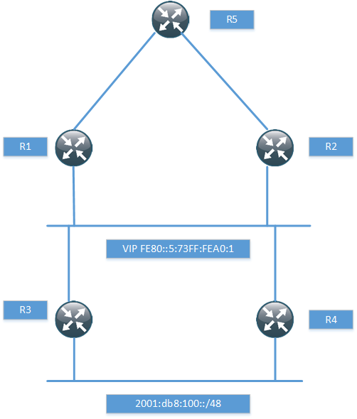
I have just setup enough of the topology to prove that it works with the next-hop, so I won’t be running any pings and so on. The routers R1 and R2 have a static route for the network behind R3 and R4.
ipv6 route 2001:DB8:100::/48 GigabitEthernet0/1 FE80::5:73FF:FEA0:1
When routing towards a link local address, the exit interface must be specified. R1 then runs BGP towards R5, notice that I’m not using next-hop-self.
router bgp 100
bgp router-id 1.1.1.1
bgp log-neighbor-changes
neighbor 2001:DB8:1::5 remote-as 100
!
address-family ipv6
redistribute static
neighbor 2001:DB8:1::5 activate
exit-address-family
If we look in the BGP RIB, we can see that the route is installed with a link local next-hop.
R1#sh bgp ipv6 uni
BGP table version is 2, local router ID is 1.1.1.1
Status codes: s suppressed, d damped, h history, * valid, > best, i - internal,
              r RIB-failure, S Stale, m multipath, b backup-path, f RT-Filter,
              x best-external, a additional-path, c RIB-compressed,
Origin codes: i - IGP, e - EGP, ? - incomplete
RPKI validation codes: V valid, I invalid, N Not found

     Network          Next Hop            Metric LocPrf Weight Path
 *>  2001:DB8:100::/48
                       FE80::5:73FF:FEA0:1
                                                0         32768 ?
What next-hop do we have at R5 though?
R5#sh bgp ipv6 uni
BGP table version is 10, local router ID is 5.5.5.5
Status codes: s suppressed, d damped, h history, * valid, > best, i - internal,
              r RIB-failure, S Stale, m multipath, b backup-path, f RT-Filter,
              x best-external, a additional-path, c RIB-compressed,
Origin codes: i - IGP, e - EGP, ? - incomplete
RPKI validation codes: V valid, I invalid, N Not found

     Network          Next Hop            Metric LocPrf Weight Path
 *>i 2001:DB8:100::/48
                       2001:DB8:1::1            0    100      0 ?
We see the next-hop of R1 and not the link local address. How did this happen? We aren’t using next-hop-self. If we debug at R1, we will see what happens.
R1#debug ip bgp updates
R1#debug ip bgp ipv6 uni
*Aug 30 06:19:15.863: BGP(1): 2001:DB8:1::5 NEXT_HOP part 1 net 2001:DB8:100::/48,
next FE80::5:73FF:FEA0:1
*Aug 30 06:19:15.863: BGP(1): Can't advertise 2001:DB8:100::/48 to 2001:DB8:1::5
with NEXT_HOP FE80::5:73FF:FEA0:1
*Aug 30 06:19:15.863: BGP(1): (base) 2001:DB8:1::5 send UPDATE (format)
2001:DB8:100::/48, next 2001:DB8:1::1, metric 0, path Local
We can see that BGP was going to advertise it with the link local next-hop but then realized that this would not work. It then replaced the link local next-hop with a global next-hop.
While it may have been true at some point that routes must point to a global next-hop, this does not hold true in modern code. BGP will automatically advertise its updates with a global next-hop.
Next Generation Multicast – NG-MVPN
Introduction
Multicast is a great technology that although it provides great benefits, is seldomly deployed. It’s a lot like IPv6 in that regard. Service providers or enterprises that run MPLS and want to provide multicast services have not been able to use MPLS to provide multicast Multicast has then typically been delivered by using Draft Rosen which is a mGRE technology to provide multicast. This post starts with a brief overview of Draft Rosen.
Draft Rosen
Draft Rosen uses GRE as an overlay protocol. That means that all multicast packets will be encapsulated inside GRE. A virtual LAN is emulated by having all PE routers in the VPN join a multicast group. This is known as the default Multicast Distribution Tree (MDT). The default MDT is used for PIM hello’s and other PIM signaling but also for data traffic. If the source sends a lot of traffic it is inefficient to use the default MDT and a data MDT can be created. The data MDT will only include PE’s that have receivers for the group in use.

Draft Rosen is fairly simple to deploy and works well but it has a few drawbacks. Let’s take a look at these:
- Overhead – GRE adds 24 bytes of overhead to the packet. Compared to MPLS which typically adds 8 or 12 bytes there is 100% or more of overhead added to each packet
- PIM in the core – Draft Rosen requires that PIM is enabled in the core because the PE’s must join the default and or data MDT which is done through PIM signaling. If PIM ASM is used in the core, an RP is needed as well. If PIM SSM is run in the core, no RP is needed.
- Core state – Unneccessary state is created in the core due to the PIM signaling from the PE’s. The core should have as little state as possible
- PIM adjacencies – The PE’s will become PIM neighbors with each other. If it’s a large VPN and a lot of PE’s, a lot of PIM adjacencies will be created. This will generate a lot of hello’s and other signaling which will add to the burden of the router
- Unicast vs multicast – Unicast forwarding uses MPLS, multicast uses GRE. This adds complexity and means that unicast is using a different forwarding mechanism than multicast, which is not the optimal solution
- Inefficency – The default MDT sends traffic to all PE’s in the VPN regardless if the PE has a receiver in the (*,G) or (S,G) for the group in use
Based on this list, it is clear that there is a room for improvement. The things we are looking to achieve with another solution is:
- Shared control plane with unicast
- Less protocols to manage in the core
- Shared forwarding plane with unicast
- Only use MPLS as encapsulation
- Fast Restoration (FRR)
NG-MVPN
To be able to build multicast Label Switched Paths (LSPs) we need to provide these labels in some way. There are three main options to provide these labels today:
- Multipoint LDP(mLDP)
- RSVP-TE P2MP
- Unicast MPLS + Ingress Replication(IR)
MLDP is an extension to the familiar Label Distribution Protocol (LDP). It supports both P2MP and MP2MP LSPs and is defined in RFC 6388.
RSVP-TE is an extension to the unicast RSVP-TE which some providers use today to build LSPs as opposed to LDP. It is defined in RFC 4875.
Unicast MPLS uses unicast and no additional signaling in the core. It does not use a multipoint LSP.
Multipoint LSP
Normal unicast forwarding through MPLS uses a point to point LSP. This is not efficient for multicast. To overcome this, multipoint LSPs are used instead. There are two different types, point to multipoint and multipoint to multipoint.

- Replication of traffic in core
- Allows only the root of the P2MP LSP to inject packets into the tree
- If signaled with mLDP – Path based on IP routing
- If signaled with RSVP-TE – Constraint-based/explicit routing. RSVP-TE also supports admission control

- Replication of traffic in core
- Bidirectional
- All the leafs of the LSP can inject and receive packets from the LSP
- Signaled with mLDP
- Path based on IP routing
Core Tree Types
Depending on the number of sources and where the sources are located, different type of core trees can be used. If you are familiar with Draft Rosen, you may know of the default MDT and the data MDT.

Signalling the Labels
As mentioned previously there are three main ways of signalling the labels. We will start by looking at mLDP.
- LSPs are built from the leaf to the root
- Supports P2MP and MP2MP LSPs
- mLDP with MP2MP provides great scalability advantages for “any to any” topologies
- “any to any” communication applications:
- mVPN supporting bidirectional PIM
- mVPN Default MDT model
- If a provider does not want tree state per ingress PE source
- “any to any” communication applications:
- mLDP with MP2MP provides great scalability advantages for “any to any” topologies
- Supports Fast Reroute (FRR) via RSVP-TE unicast backup path
- No periodic signaling, reliable using TCP
- Control plane is P2MP or MP2MP
- Data plane is P2MP
- Scalable due to receiver driven tree building
- Supports MP2MP
- Does not support traffic engineering
RSVP-TE can be used as well with the following characteristics.
- LSPs are built from the head-end to the tail-end
- Supports only P2MP LSPs
- Supports traffic engineering
- Bandwidth reservation
- Explicit routing
- Fast Reroute (FRR)
- Signaling is periodic
- P2P technology at control plane
- Inherits P2P scaling limitations
- P2MP at the data plane
- Packet replication in the core
RSVP-TE will mostly be interesting for SPs that are already running RSVP-TE for unicast or for SPs involved in video delivery. The following table shows a comparision of the different protocols.

Assigning Flows to LSPs
After the LSPs have been signalled, we need to get traffic onto the LSPs. This can be done in several different ways.
- Static
- PIM
- RFC 6513
- BGP Customer Multicast (C-Mcast)
- RFC 6514
- Also describes Auto-Discovery
- mLDP inband signaling
- RFC 6826
Static
- Mostly applicable to RSVP-TE P2MP
- Static configuration of multicast flows per LSP
- Allows aggregation of multiple flows in a single LSP
PIM
- Dynamically assigns flows to an LSP by running PIM over the LSP
- Works over MP2MP and PPMP LSP types
- Mostly used but not limited to default MDT
- No changes needed to PIM
- Allows aggregation of multiple flows in a single LSP
BGP Auto-Discovery
- Auto-Discovery
- The process of discovering all the PE’s with members in a given mVPN
- Used to establish the MDT in the SP core
- Can also be used to discover set of PE’s interested in a given customer multicast group (to enable S-PSMSI creation)
- S-PMSI = Data MDT
- Used to advertise address of the originating PE and tunnel attribute information (which kind of tunnel)
BGP MVPN Address Family
- MPBGP extensions to support mVPN address family
- Used for advertisement of AD routes
- Used for advertisement of C-mcast routes (*,G) and (S,G)
- Two new extended communities
- VRF route import – Used to import mcast routes, similar to RT for unicast routes
- Source AS – Used for inter-AS mVPN
- New BGP attributes
- PMSI Tunnel Attribute (PTA) – Contains information about advertised tunnel
- PPMP label attribute – Upstream generated label used by the downstream clients to send unicast messages towards the source
- If mVPN address family is not used the address family ipv4 mdt must be used
BGP Customer Multicast
- BGP Customer Multicast (C-mcast) signalling on overlay
- Tail-end driven updates is not a natural fit for BGP
- BGP is more suited for one-to-many not many-to-one
- PIM is still the PE-CE protocol
- Easy to use with SSM
- Complex to understand and troubleshoot for ASM
MLDP Inband Signaling
- Multicast flow information encoded in the mLDP FEC
- Each customer mcast flow creates state on the core routers
- Scaling is the same as with default MDT with every C-(S,G) on a Data MDT
- IPv4 and IPv6 multicast in global or VPN context
- Typical for SSM or PIM sparse mode sources
- IPTV walled garden deployment
- RFC 6826
The natural choice is to stick with PIM unless you need very high scalability. Here is a comparison of PIM and BGP.

BGP C-Signaling
- With C-PIM signaling on default MDT models, data needs to be monitored
- On default/data tree to detect duplicate forwarders over MDT and to trigger the assert process
- On default MDT to perform SPT switchover (from (*,G) to (S,G))
- On default MDT models with C-BGP signaling
- There is only one forwarder on MDT
- There are no asserts
- The BGP type 5 routes are used for SPT switchover on PEs
- There is only one forwarder on MDT
- Type 4 leaf AD route used to track type 3 S-PMSI (Data MDT) routes
- Needed when RR is deployed
- If source PE sets leaf-info-required flag on type 3 routes, the receiver PE responds with with a type 4 route
Migration
If PIM is used in the core, this can be migrated to mLDP. PIM can also be migrated to BGP. This can be done per multicast source, per multicast group and per source ingress router. This means that migration can be done gradually so that not all core trees must be replaced at the same time.
It is also possible to have both mGRE and MPLS encapsulation in the network for different PE’s.
To summarize the different options for assigning flows to LSPs
- Static
- Mostly applicable to RSVP-TE
- PIM
- Well known, has been in use since mVPN introduction over GRE
- BGP A-D
- Useful where head-end assigns the flows to the LSP
- BGP C-mcast
- Alternative to PIM in mVPN context
- May be required in dual vendor networks
- MLDP inband signaling
- Method to stitch a PIM tree to a mLDP LSP without any additional signaling
Optimizing the MDT
There are some drawbacks with the normal operation of the MDT. The tree is signalled even if there is no customer traffic leading to unneccessary state in the core. To overcome these limitations there is a model called the partitioned MDT running over mLDP with the following characteristics.
- Dynamic version of default MDT model
- MDT is only built when customer traffic needs to be transported across the core
- It addresses issues with the default MDT model
- Optimizes deployments where sources are located in a few sites
- Supports anycast sources
- Default MDT would use PIM asserts
- Reduces the number of PIM neighbors
- PIM neighborship is unidirectional – The egress PE sees ingress PEs as PIM neighbors
Conclusion
There are many many different profiles supported, currently 27 profiles on Cisco equipment. Here are some guidelines to guide you in the selection of a profile for NG-MVPN.
- Label Switched Multicast (LSM) provides unified unicast and multicast forwarding
- Choosing a profile depends on the application and scalability/feature requirements
- MLDP is the natural and safe choice for general purpose
- Inband signalling is for walled garden deployments
- Partitioned MDT is most suitable if there are few sources/few sites
- P2MP TE is used for bandwidth reservation and video distribution (few source sites)
- Default MDT model is for anyone (else)
- PIM is still used as the PE-CE protocol towards the customer
- PIM or BGP can be used as an overlay protocol unless inband signaling or static mapping is used
- BGP is the natural choice for high scalability deployments
- BGP may be the natural choice if already using it for Auto-Discovery
- The beauty of NG-MVPN is that profile can be selected per customer/VPN
- Even per source, per group or per next-hop can be done with Routing Policy Language (RPL)
This post was heavily inspired and is basically a summary of the Cisco Live session BRKIPM-3017 mVPN Deployment Models by Ijsbrand Wijnands and Luc De Ghein. I recommend that you read it for more details and configuration of NG-MVPN.
Noction Intelligent Routing Platform (IRP) – What is it?
I was contacted by some people at Noction and asked if I was interested in writing about their platform, the Intelligent Routing Platform (IRP). Since it’s a product that uses Border Gateway Protocol (BGP), it peaked my interest. First let’s make the following things clear:
- I am not being paid to write this blog post
- My opinions can’t be bought
- I will only write about a product if it’s something that interests me
BGP is the glue of the Internet (with DNS) and what keeps everything running. BGP is a well designed and scalable protocol which has been around for a long time. It has grown from carrying a few hundred routes to half a million routes. However, there will always be use cases where BGP might not fit your business model.
In Noction’s white paper they define the following as the network’s major challenges:
- Meeting the customer’s demand for 100% uptime
- Facing the low latency requirement
- Achieving reliable data transmission
- Avoiding network congestion and blackouts
- Achieving consistency of throughput
- Keeping bandwidth usage below predefined commit levels
- Reducing the cost and time of network troubleshooting
The product is designed for multihomed networks running BGP. You can’t optimize network flows if you don’t have any other paths to switch to. Some of these challenges apply to all networks and some may be a bit more local. As an example, in Sweden (where I live), you usually pay a fixed amount for your bandwidth and you can use that all you want without going above some threshold defined by the Service Provider (SP).
So why do we have these challenges? Is it BGP’s fault? BGP has a lot of knobs but they are quite blunt tools. We need to keep in mind that BGP runs between organizations and every organization must make their own decisions on how to forward traffic. This means that there is no end to end policy to optimize the traffic flowing across these organizations.
If history has learned us anything, it is that protocols that try to keep too much state will eventually fail or hit scaling limitations. These protocols seem very intelligent and forward thinking at first but as soon as they hit large scale, the burden becomes too much. One such protcol is Resource Reservation Protocol (RSVP). BGP’s design is what has kept the Internet running for decades, this would not be the case if we were to inject all kind of metrics, latencies, jitter etc for all of the Network Layer Reachability Information (NLRI). As communities have grown more popular there could be a use case where information is tagged along as communities for the NLRI. The question is then, how often do we update the communities?
Does this mean that these are not real challenges or that there is no room for a product like Noction IRP? No, it means that unique forwarding decisions and intelligence needs to be kept at the edge of the network, not in the core. We should keep as little state as possible in the core for networks that need high availability.
How does BGP select which routes are the best? The default is to simply look at the AS-path:, the shorter AS-path, the better. Meaning that the traffic will pass through as few organizations as possible. This does not however give any consideration to how much bandwidth is available, nor takes into account latency and jitter of the path and the availability of the path.
How does this product work? The following picture shows the key components of IRP:

There is a collector that passively analyzes the traffic flowing to see which prefixes are being used the most, between which endpoints is the traffic flowing and so on. The collector can gather this data from a mirror port or preferably from Netflow/sFlow.
The Explorer will actively probe relevant prefixes for metrics such as latency, jitter and packet loss. This data is then sent to the Core.
The Core is based on the data received from the Explorer calculating improvements to optimize metrics such as latency, jitter and packet loss or the most cost effective path. These improvements are sent to the BGP daemon which will advertise BGP Updates to the edge router(s).
IRP is non-intrusive and does not sit in the data path. If IRP were to fail, traffic would fall back to their normal paths following the shortest AS-path or any other policies defined on the edge router. IRP can also act in BGP non-intrusive mode where it will report potential improvements without applying them.
If we pause here for a second, this sounds a lot like Performance Routing (PfR), doesn’t it? So what value would IRP add that PfR does not? I see mainly two benefits here. PfR may require a more senior network administrator to setup and administer, however PfR has been greatly simplified in later releases. The other main factor is the reporting through the frontend. PfR does not give you the monitoring platform, which is not to be expected of course.
When you login to the IRP you get a dashboard showing the status of the system and the number of prefixes being probed and how many of those prefixes are being improved.

In the demo, there are two service providers called “SwiftWay” and “FiberRing”. There is a graph to show how many prefixes have been rerouted to one of the providers.

There is also a list that shows you which prefixes were moved, what’s the AS number and the reason for being moved. If you do a mouseover on the flash symbol, it will show if the improvement was due to loss or latency.

There are a lot of different reports that can be generated. A nice feature is that all reports are exportable to CSV, XLS or PDF.

This report shows how loss has been improved: 75% of loss was totally avoided and 25% of loss was reduced.

There are also graphs showing top usage of traffic by AS or, as in this case, the bandwidth used per provider.

The monitoring and reports are extensive and easy to use. The IRP is certainly an interesting platform and depending on the business case it could be very useful. The main considerations would be how sensitive are you to loss and latency? How much does it cost you if you are not choosing the most optimal path? Do you trust a system to make these decisions for you? If you do, then certainly take a look at the Noction IRP.
Unique RD per PE in MPLS VPN for Load Sharing and Faster Convergence
This post describes how load sharing and faster convergence in MPLS VPNs is possible by using an unique RD per VRF per PE. It assumes you are already familiar with MPLS but here is a quick recap.
The Route Distinguisher (RD) is used in MPLS VPNs to create unique routes. With IPv4, an IP address is 32 bits long but several customers may and probably will use the same networks. If CustomerA uses 10.0.0.0/24 and CustomerX also uses 10.0.0.0/24, we must in some way make this route unique to transport it over MPBGP. The RD does exactly this by prepending a 64 bit value and together with the IPv4 address, creating a 96-bit VPNv4 prefix. This is all the RD does, it has nothing to do with the VPN in itself. It is common to create RD consisting of AS_number:VPN_identifier so that a VPN has the same RD on all PEs where it exists.
The Route Target (RT) is what defines the VPN, which routes are imported to the VPN and the topology of the VPN. These are extended communities that are tagged on to the BGP Update and transported over MPBGP.
MPLS uses labels, the transport label which is used to transport the packet through the network is generated by LDP. The VPN label which is used to make sure the packets make it to the right VPN is generated by MPBGP and can be per prefix or per VRF.
Below is a configuration snipper for creating a VRF with the newer syntax that is used.
PE1#sh run vrf
Building configuration...

Current configuration : 401 bytes
vrf definition CUST1
 rd 11.11.11.11:1
 !
 address-family ipv4
  route-target export 64512:1
  route-target import 64512:1
 exit-address-family
!
!
interface GigabitEthernet1
 vrf forwarding CUST1
 ip address 111.0.0.0 255.255.255.254
 negotiation auto
!
router bgp 64512
 !
 address-family ipv4 vrf CUST1
  neighbor 111.0.0.1 remote-as 65000
  neighbor 111.0.0.1 activate
 exit-address-family
!
end
The values for the RD and RT are defined under the VRF. Now the topology we will be using is the one below.

This topology uses a Route Reflector (RR) like most decently sized net works will to overcome the scalability limitations of a BGP full mesh. The negative part of using a RR is that we will have less routes because only the best routes will be reflected. This means that load sharing may not take place and that convergence takes longer time when a link between a PE and a CE goes down.
This diagram shows PE1 and PE2 advertising the same network 10.0.10.0/24 to the RR. The RR then picks one as best and reflects that to PE3 (and others). This means that the path through PE2 will never be used until something happens with PE1. This is assuming that they are both using the same RD.


When PE1 loses its prefix it sends a BGP WITHDRAW to the RR, the RR then sends a WITHDRAW to PE3 and then it sends an UPDATE which is the prefix via PE2. The path via PE2 is not used until this happens. This means that load sharing is not taking place and that all traffic destined for 10.0.10.0/24 has to converge.
If every PE is using unique RD for the VRF per PE then they become two different routes and both can be reflected by the RR. The RD is then usually written in the form PE_loopback:VPN_identifier. This also helps with troubleshooting to see where the prefix originated from.

PE3 now has two routes to 10.0.10.0/24 in its routing table.
PE3#sh ip route vrf CUST1 10.0.10.0 255.255.255.0

Routing Table: CUST1
Routing entry for 10.0.10.0/24
  Known via "bgp 64512", distance 200, metric 0
  Tag 65000, type internal
  Last update from 11.11.11.11 01:10:52 ago
  Routing Descriptor Blocks:
  * 22.22.22.22 (default), from 111.111.111.111, 01:10:52 ago
      Route metric is 0, traffic share count is 1
      AS Hops 1
      Route tag 65000
      MPLS label: 17
      MPLS Flags: MPLS Required
    11.11.11.11 (default), from 111.111.111.111, 01:10:52 ago
      Route metric is 0, traffic share count is 1
      AS Hops 1
      Route tag 65000
      MPLS label: 28
      MPLS Flags: MPLS Required
The PE is now doing load sharing meaning that some traffic will take the path over PE1 and some over PE2.

We have achieved load sharing and this also means that if something happens with PE1 or PE2, not all traffic will be effected. To see which path is being used from PE3 we can use the show ip cef exact-route command.
PE3#sh ip cef vrf CUST1 exact-route 10.0.0.10 10.0.10.1
10.0.0.10 -> 10.0.10.1 => label 17 label 16TAG adj out of GigabitEthernet1, addr 23.23.23.0
PE3#sh ip cef vrf CUST1 exact-route 10.0.0.5 10.0.10.1
10.0.0.5 -> 10.0.10.1 => label 28 label 17TAG adj out of GigabitEthernet1, addr 23.23.23.0
What is the drawback of using this? It consumes more memory because the prefixes are now unique, in effect doubling the required memory to store BGP Paths. The PEs have to store several copies with different RD for the prefix before it can import it into the RIB.
PE3#sh bgp vpnv4 uni all
BGP table version is 46, local router ID is 33.33.33.33
Status codes: s suppressed, d damped, h history, * valid, > best, i - internal,
              r RIB-failure, S Stale, m multipath, b backup-path, f RT-Filter,
              x best-external, a additional-path, c RIB-compressed,
Origin codes: i - IGP, e - EGP, ? - incomplete
RPKI validation codes: V valid, I invalid, N Not found

     Network          Next Hop            Metric LocPrf Weight Path
Route Distinguisher: 11.11.11.11:1
 *>i 10.0.10.0/24     11.11.11.11              0    100      0 65000 i
Route Distinguisher: 22.22.22.22:1
 *>i 10.0.10.0/24     22.22.22.22              0    100      0 65000 i
Route Distinguisher: 33.33.33.33:1 (default for vrf CUST1)
 *>  10.0.0.0/24      32.32.32.1               0             0 65001 i
 *mi 10.0.10.0/24     22.22.22.22              0    100      0 65000 i
 *>i                  11.11.11.11              0    100      0 65000 i
For the multipathing to take place, PE3 must allow more than one route to be installed via BGP. This is done through the maximum-paths eibgp command.
address-family ipv4 vrf CUST1
  maximum-paths eibgp 2
In newer releases there are other features to overcome the limitation of only reflecting one route, such as BGP Add Path. This post showed the benefits of enabling unique RD for a VRF per PE to enable load sharing and better convergence. It also showed that doing so will use more memory due to having to store multiple copies of essentially the same route. Because multiple routes get installed into the FIB, that should also be a consideration depending on how large the FIB is for your platform.
Some pointers on OSPF as PE to CE protocol
There was a discussion at the Cisco Learning Network (CLN) about OSPF as PE to CE
protocol. I wanted to provide some pointers on using OSPF as PE to CE protocol.
RFC 4577 describes how to use OSPF as PE to CE protocol. When using BGP to carry the
OSPF routes the MPLS backbone is seen as a super backbone. This adds another level of
hierarchy making OSPF three levels compared to the usual two when using plain OSPF.

Because the the MPLS backbone is seen as a super area 0, that means that OSPF routes
going across the MPLS backbone can never be better than type 3 summary LSA. Even if
the same area is used on both sides of the backbone and the input is a type 1 or type 2
LSA it will be advertised as a summary LSA on the other side.

The only way to keep the type 1 or type 2 LSAs as they are is to use a sham link.
Sham links sets up a control plane mechanism acting as a tunnel for the LSAs passing
over the MPLS backbone. Sham links are outside the scope of this article.
A LSA can never be “better” than it originally was input as. This means that if the input
to the PE isa type 3 LSA this can never be converted to a type 1 or type 2 LSA on the other
side. If the LSA was type 5 external to begin it will be sent as type 5 on the other side
as well.
To understand how the LSAs are sent over the backbone, look at this picture.

OSPF LSA is sent to PE which is running OSPF in a VRF with the CPE. The PE installs
the LSA as a route in the OSPF RIB. If the route is the best one known to the router
it can install it to the global RIB.
The PE redistributes from OSPF into BGP. Only routes that are installed as OSPF in
the RIB will be redistributed. To be able to carry OSPF specific information the PE
has to add extended communities. To make the IPv4 route a VPNv4 route the PE has
to add the RD and RT values. The OSPF specific communities consist of:
Domain-ID
The domain ID can either be hard coded or derived from the OSPF process running.
It is used to identify if LSAs are sent into the same domain as they originated
from. If the domain ID matches then type 3 summary LSAs can be sent for routes
that were internal or inter area. If the domain ID does not match then all routes
must be sent as external.
Domain ID match

Domain ID non match

OSPF Route Type
The route type consists of area number, route type and options.

If we look at a MPBGP update we can see the route type encoded.
R4#sh bgp vpnv4 uni rd 1:1 1.1.1.1/32
BGP routing table entry for 1:1:1.1.1.1/32, version 5
Paths: (1 available, best #1, table cust)
Flag: 0x820
  Not advertised to any peer
  Local
    2.2.2.2 (metric 21) from 2.2.2.2 (2.2.2.2)
      Origin incomplete, metric 11, localpref 100, valid, internal, best
      Extended Community: RT:1:1 OSPF DOMAIN ID:0x0005:0x000000020200
        OSPF RT:0.0.0.0:2:0 OSPF ROUTER ID:22.22.22.22:0
      mpls labels in/out nolabel/18
Something that is a bit peculiar is that this update has a route type of 2 even though
it originated from a type 1 LSA. In the end it doesn’t make a difference because it will
be advertised as type 3 LSA to the CPE.
OSPF Router ID
The router ID of the router that originated the LSA (PE) is also carried as an extended
community.
R4#sh bgp vpnv4 uni rd 1:1 1.1.1.1/32
BGP routing table entry for 1:1:1.1.1.1/32, version 5
Paths: (1 available, best #1, table cust)
Flag: 0x820
  Not advertised to any peer
  Local
    2.2.2.2 (metric 21) from 2.2.2.2 (2.2.2.2)
      Origin incomplete, metric 11, localpref 100, valid, internal, best
      Extended Community: RT:1:1 OSPF DOMAIN ID:0x0005:0x000000020200
        OSPF RT:0.0.0.0:2:0 OSPF ROUTER ID:22.22.22.22:0
      mpls labels in/out nolabel/18
MED
The MED is set to the OSPF metric + 1 as defined by the RFC.
R4#sh bgp vpnv4 uni rd 1:1 1.1.1.1/32
BGP routing table entry for 1:1:1.1.1.1/32, version 5
Paths: (1 available, best #1, table cust)
Flag: 0x820
  Not advertised to any peer
  Local
    2.2.2.2 (metric 21) from 2.2.2.2 (2.2.2.2)
      Origin incomplete, metric 11, localpref 100, valid, internal, best
      Extended Community: RT:1:1 OSPF DOMAIN ID:0x0005:0x000000020200
        OSPF RT:0.0.0.0:2:0 OSPF ROUTER ID:22.22.22.22:0
      mpls labels in/out nolabel/18
The goal of these extended communities is to extend BGP so that OSPF LSAs can be
carried transparently as if BGP hadn’t been involved at all. LSAs are translated
to BGP updates and then translated back to LSAs.
If we look at a packet capture we can see the extended communities attached.
This BGP Update originated from a type 5 external LSA with metric-type 1.

When using OSPF as the PE to CE protocol it is important to remember the design
rules of OSPF. Because of that you should avoid designs like this:

In this design area 1 is used on both sides but the CPE is then connected to area 0
which makes it an ABR. The rules of OSPF dictate that summary LSAs must only be
received over area 0 if it is an ABR. This means this topology is broken and would
require changing area or using a virtual link.
OSPF as PE to CE protocol has some complexity but must of it is still plain OSPF
which is in itself a complicated protocol. Combine that with BGP and MPLS and
it is easy to get confused which protocol is responsible for what. That is also
one of the reasons that I recommend to use eBGP or static when customers connect
to their ISP.
Scaling PEs in MPLS VPN – Route Target Constraint (RTC)
Introduction
In any decent sized service provider or even an enterprise network running
MPLS VPN, it will most likely be using Route Reflectors (RR). As described in
a previous post iBGP fully meshed does not really scale. By default all
PEs will receive all routes reflected by the RR even if the PE does not
have a VRF configured with an import matching the route. To mitigate this
ineffecient behavior Route Target Constraint (RTC) can be configured. This
is defined in RFC 4684.
Route Target Constraint
The way this feature works is that the PE will advertise to the RR which RTs
it intends to import. The RR will then implement an outbound filter only sending
routes matching those RTs to the PE. This is much more effecient than the default
behavior. Obviously the RR still needs to receive all the routes so no filtering
is done towards the RR. To enable this feature a new Sub Address Family (SAFI) is
used called rtfilter. To show this feature we will implement the following topology.

The scenario here is that PE1 is located in a large PoP where there are already plenty
of customers. It currently has 255 customers. PE2 is located in a new PoP and so far only
one customer is connected there. It’s unneccessary for the RR to send all routes to PE2
for all of PE1 customers because it does not need them. To simulate the customers I wrote
a simple bash script to create the VRFs for me in PE1.
#!/bin/bash
for i in {0..255}
do
   echo "ip vrf $i"
   echo "rd 1:$i"
   echo "route-target 1:$i"
   echo "interface loopback$i"
   echo "ip vrf forwarding $i"
   echo "ip address 10.0.$i.1 255.255.255.0"
   echo "router bgp 65000"
   echo "address-family ipv4 vrf $i"
   echo "network 10.0.$i.0 mask 255.255.255.0"
done
PE2 will not import these due to that the RT is not matching any import statements in
its only VRF that is currently configured. If we debug BGP we can see lots of messages
like:
BGP(4): Incoming path from 4.4.4.4
BGP(4): 4.4.4.4 rcvd UPDATE w/ attr: nexthop 1.1.1.1, origin i, localpref 100,
metric 0, originator 1.1.1.1, clusterlist 4.4.4.4, extended community RT:1:104
BGP(4): 4.4.4.4 rcvd 1:104:10.0.104.0/24, label 120 -- DENIED due to:  extended
community not supported;
In this case we have 255 routes but what if it was 1 million routes? That would be
a big waste of both processing power and bandwidth, not to mention that the RR would
have to format all the BGP updates. These are the benefits of enabling RTC:
- Eliminating waste of processing power on PE and RR and waste of bandwidth
- Less VPNv4 formatted Updates
- BGP convergence time is reduced
Currently the RR is advertising 257 prefixes to PE2.
RR#sh bgp vpnv4 uni all neighbors 3.3.3.3 advertised-routes | i Total
Total number of prefixes 257
Implementation
Implementing RTC is simple. It has to be supported on both the RR and the PE though.
Add the following commands under BGP:
RR:
RR(config)#router bgp 65000
RR(config-router)#address-family rtfilter unicast
RR(config-router-af)#nei 3.3.3.3 activate
RR(config-router-af)#nei 3.3.3.3 route-reflector-client
PE2:
PE2(config)#router bgp 65000
PE2(config-router)#address-family rtfilter unicast
PE2(config-router-af)#nei 4.4.4.4 activate
The BGP session will be torn down when doing this! Now to see how many routes the RR is
sending.
RR#sh bgp vpnv4 uni all neighbors 3.3.3.3 advertised-routes | i Total
Total number of prefixes 0
No prefixes! To see the rt filter in effect use this command:
RR#sh bgp rtfilter unicast all
BGP table version is 3, local router ID is 4.4.4.4
Status codes: s suppressed, d damped, h history, * valid, > best, i - internal,
              r RIB-failure, S Stale, m multipath, b backup-path, f RT-Filter,
              x best-external, a additional-path, c RIB-compressed,
Origin codes: i - IGP, e - EGP, ? - incomplete
RPKI validation codes: V valid, I invalid, N Not found

     Network          Next Hop            Metric LocPrf Weight Path
     0:0:0:0          0.0.0.0                                0 i
 *>i 65000:2:1:256    3.3.3.3                  0    100  32768 i
Now we add an import under the VRF in PE2 and one route should be sent.
PE2(config)#ip vrf 0
PE2(config-vrf)#route-target import 1:1
PE2#sh ip route vrf 0

Routing Table: 0
Codes: L - local, C - connected, S - static, R - RIP, M - mobile, B - BGP
       D - EIGRP, EX - EIGRP external, O - OSPF, IA - OSPF inter area
       N1 - OSPF NSSA external type 1, N2 - OSPF NSSA external type 2
       E1 - OSPF external type 1, E2 - OSPF external type 2
       i - IS-IS, su - IS-IS summary, L1 - IS-IS level-1, L2 - IS-IS level-2
       ia - IS-IS inter area, * - candidate default, U - per-user static route
       o - ODR, P - periodic downloaded static route, H - NHRP, l - LISP
       + - replicated route, % - next hop override

Gateway of last resort is not set

      10.0.0.0/8 is variably subnetted, 3 subnets, 2 masks
B        10.0.1.0/24 [200/0] via 1.1.1.1, 00:00:16
C        10.1.1.0/24 is directly connected, Loopback1
L        10.1.1.1/32 is directly connected, Loopback1
RR#sh bgp vpnv4 uni all neighbors 3.3.3.3 advertised-routes | i Total
Total number of prefixes 1
RR#sh bgp rtfilter unicast all
BGP table version is 4, local router ID is 4.4.4.4
Status codes: s suppressed, d damped, h history, * valid, > best, i - internal,
              r RIB-failure, S Stale, m multipath, b backup-path, f RT-Filter,
              x best-external, a additional-path, c RIB-compressed,
Origin codes: i - IGP, e - EGP, ? - incomplete
RPKI validation codes: V valid, I invalid, N Not found

     Network          Next Hop            Metric LocPrf Weight Path
     0:0:0:0          0.0.0.0                                0 i
 *>i 65000:2:1:1      3.3.3.3                  0    100  32768 i
 *>i 65000:2:1:256    3.3.3.3                  0    100  32768 i
Works as expected. From the output we can see that the AS is 65000, the extended
community type is 2 and the RT that should be exported is 1:1 and 1:256.
Conclusion
Route Target Constraint is a powerful feature that will lessen the load on both your
Route Reflectors and PE devices in an MPLS VPN enabled network. It can also help
with making BGP converging faster. Support is needed on both PE and RR and the BGP
session will be torn down when enabling it so it has to be done during maintenance
time.
iBGP – Fully meshed vs Route Reflection
Intro
This post looks at the pros and cons with BGP Route Reflection compared to running
an iBGP full mesh.
Full mesh
Because iBGP routes are not propagated to iBGP sessions there must be a full mesh
inside the BGP network. This leads to scalability issues. For every N routers
there will be (N-1) iBGP neighbors and (N*(N-1))/2 BGP sessions. For a medium
sized ISP network with 100 routers running BGP this would be 99 iBGP neighbors
and 4950 BGP sessions in total.

There are 4 routers in AS 2 which gives 3 iBGP neighbors and 6 iBGP sessions in total.
Benefits of a full mesh:
- Optimal Traffic Forwarding
- Path Diversity
- Convergence
- Robustness
Optimal Traffic Forwarding:
Because all BGP speaking routers are fully meshed they will receive iBGP updates
from all peers. If no manipulating of attributes have been done then the tiebreaker
will be the metric to the next-hop (IGP) so traffic will take the optimal path.
Path Diversity:
Due to the full mesh the BGP speaking router will have multiple paths to choose
from. If it was connected to a RR it would generally only have one path, the one
the RR decided was the best.
Convergence:
Because the BGP speaking router has multiple paths if the current best one should fail
it can start using one of the alternate paths. Also the BGP UPDATE messages are sent
directly between the iBGP peers instead of passing through an additional router (RR)
which would have to process it and the packets would have to travel additional distance
unless the RR is located in the same PoP as the routers.
Robustness:
If one BGP speaking router fails then only the networks behind that router are
not reachable any longer. If a RR fails then all networks that were reachable via
clients to that RR would no longer be reachable.
Caveats of a full mesh:
- Lack of Scalability
- Management Overhead
- Duplication of Information
Lack of Scalability:
Having hundreds of BGP sessions on all routers would mean a lot of BGP processing.
The number of BGP Updates coming in would be massive.
This would put a great burden on the CPU/RP of the router. For really large networks
this could potentially be more than the router can handle. In a network with 300 routers
there would be 44850 iBGP sessions. The RIB-in size would be very large because of the
large number of peers.
Management Overhead:
Adding a new device to the network means reconfiguring all the existing devices.
Configurations would be very big considering all the lines needed to setup the
full mesh.
Duplication of Information:
For every external network there could potentially be multiple paths internally
leading to using lots of RIB/FIB space on the devices. It does not make much sense
to install all paths into RIB/FIB.
Benefits of Route Reflection:
- Scalability
- Reduced Operational Cost
- Reduced RIB-in Size
- Reduced Number of BGP Updates
- Incremental Deployability
Scalability:
The number of iBGP sessions needed is greatly reduced. A client only needs one session
or preferably two to have route reflector redundancy. A route reflector needs
(K*(K-1))/2 + C where K is the number of route reflectors and C is the number of
clients. The route reflectors still need to be in full mesh with each other.
Reduced Operational Cost:
With a full mesh when adding a new device it requires reconfiguring all the existing
devices. This requires operator intervention which is an added cost. With route reflection
when adding a new device only the new device and the RR it peers with needs new configuration.
Reduced RIB-in Size:
RIB-in contains the unprocessed BGP information. After processing this information
the best paths are installed into the Loc-RIB. The RIB-in grows proportionally with
the number of neighbors that the router peers with. If there is n routers and p prefixes
then the router would have a RIB-in that is of size n * p. In a full mesh n is very high
but with route reflection n is only the number of RRs that the router peers with.
Reduced Number of BGP Updates:
In a full mesh a router will receive N – 1 updates where N is the number of routers.
This is a large amount of updates. With route reflection N is small since this is
only the number of route reflectors the router peers with.
Incremental Deployability:
Route reflection does not require massive changes in the existing network like with
confederations. It can be deployed incrementally and routers can be migrated to the
RR topology gradually. Not all routers need to be moved at once.
Caveats of Route Reflection:
- Robustness
- Prolonged Routing Convergence
- Potential Loops
- Reduced Path Diversity
- Suboptimal Routes
Robustness:
With a full mesh if a single router fails that only impacts the networks behind
that router. If a route reflector fails it affects all the networks that were
behind all of the route reflectors clients. To avoid single points of failure,
RRs are usually deployed in pairs.
Prolonged Routing Convergence:
In a full mesh every BGP update only travels a single hop. With route reflection
the number of hops is increased and if the route reflectors are setup in a
hierarchical topology the update could travel through several RRs. Every RR
will add some processing delay and propagation delay before the update reaches
the client.
Potential Loops:
In a topology where clients are connected to a single RR there should be no
data plane loops. When clients are connected to two RRs there is a risk
of a loop forming if the control plane topology does not match the physical
topology. Because of that it is important to try to match the two topologies.
Reduced Path Diversity:
In a full mesh if there are multiple paths to an external network then
all paths will be announced and the local router makes a decision which one
is the best. With route reflection the RR makes the decision which path is
the best and announces this path only. This leads to fewer paths being
announced which could lead to longer convergence delays.
There are drafts for announcing more than one best path which would help
with this issue. Some newer IOS releases supports this feature.
Suboptimal routes:
The RR will select a best path based on its own local routing information.
This could lead to routers using suboptimal paths because there may be
a shorter path available from a routers perspective but this is not the
path that the RR had chosen. Therefore it’s important to consider where
the RRs are placed.
Conclusion
This post takes a look at the benefits and caveats of a fully meshed iBGP network
vs route reflection. Although because of scalability it’s almost impossible to not
go with route reflection one should still consider the caveats of route reflection.
It’s important to consider the placement and the number of RRs in the topology.
This post is the first of posts that will focus on CCDE topics.
BGP wedgies – Why isn’t my routing policy having effect?
Intro
Brian McGahan from INE introduced me to something interesting the other day.
BGP wedgie, what is that? I had never heard of it before although I’ve heard
of such things occuring. A BGP wedgie is when a BGP configuration can lead
to different end states depending on in which order routes are sent. There is
actually an RFC for this – RFC 4264.
Peering relationships
To understand this RFC you need to have some knowledge of BGP and the different
kind of peering relationships between service providers and customers.
Service providers are usually described as Tier 1 or Tier 2. A Tier 1 service provider
is one that does not need to buy transit. They have private peerings with other service
providers to reach all networks in the Default Free Zone (DFZ). This is the
theory although it’s difficult in the real world to see who is Tier 1 or not.
Tier 2 service providers don’t have private peerings to reach all the networks so they
must buy transit from one or more Tier 1 service providers. This is a paid
service.
Service providers have different preference for routes coming in. The most
preferred routes are those coming from customers. After that it is preferred
to send traffic over private peerings since in theory this should be cheaper than
transit. The least preferred is to send traffic towards your transit.
Why is my policy not working?
Assume that you are a customer buying capacity from two service providers.
You want to use one service provider as primary and one as secondary.
This is usually done by sending a community towards your secondary provider
which then sets local preference. Keep in mind that providers will still have
their best economic result in mind though. Take a look at the following diagram.

We will be configuring AS1. We want to have the network 1.1.1.0/24 as primary
by AS4 and secondary by AS2. We will use communities to achieve this. We
setup the primary path first.
This is the configuration of AS1 so far:
router bgp 1
 no synchronization
 bgp log-neighbor-changes
 neighbor 12.12.12.2 remote-as 2
 neighbor 12.12.12.2 description backup
 neighbor 12.12.12.2 shutdown
 neighbor 12.12.12.2 send-community
 neighbor 12.12.12.2 route-map set-backup out
 neighbor 14.14.14.4 remote-as 4
 neighbor 14.14.14.4 description primary
 no auto-summary
!
ip bgp-community new-format
!
route-map set-backup permit 10
 set community 2:50
The backup will be turned up later.
Looking from AS2 perspective we now have the correct path.
AS2#sh bgp ipv4 uni
BGP table version is 2, local router ID is 23.23.23.2
Status codes: s suppressed, d damped, h history, * valid, > best, i - internal,
              r RIB-failure, S Stale
Origin codes: i - IGP, e - EGP, ? - incomplete

   Network          Next Hop            Metric LocPrf Weight Path
*> 1.1.1.0/24       23.23.23.3                             0 3 4 1 i
AS2#traceroute 1.1.1.1

Type escape sequence to abort.
Tracing the route to 1.1.1.1

  1 AS3 (23.23.23.3) 80 msec 36 msec 20 msec
  2 AS4 (34.34.34.4) 64 msec 56 msec 48 msec
  3 AS1 (14.14.14.1) 84 msec *  68 msec
Now the backup service is turned up.
AS1(config-router)#no nei 12.12.12.2 shut
AS1(config-router)#
%BGP-5-ADJCHANGE: neighbor 12.12.12.2 Up
AS2 still prefers the correct path due to local preference.
AS2#sh bgp ipv4 uni
BGP table version is 2, local router ID is 23.23.23.2
Status codes: s suppressed, d damped, h history, * valid, > best, i - internal,
              r RIB-failure, S Stale
Origin codes: i - IGP, e - EGP, ? - incomplete

   Network          Next Hop            Metric LocPrf Weight Path
*  1.1.1.0/24       12.12.12.1               0     50      0 1 i
*>                  23.23.23.3                             0 3 4 1 i
AS2#traceroute 1.1.1.1

Type escape sequence to abort.
Tracing the route to 1.1.1.1

  1 AS3 (23.23.23.3) 84 msec 44 msec 20 msec
  2 AS4 (34.34.34.4) 56 msec 60 msec 44 msec
  3 AS1 (14.14.14.1) 100 msec *  100 msec
AS3 and AS4 has the following route-map to increase local pref for customer
routes.
AS3#sh route-map
route-map customer, permit, sequence 10
  Match clauses:
  Set clauses:
    local-preference 150
  Policy routing matches: 0 packets, 0 bytes
Now what happens if there is a failure between AS1 and AS4?
AS2 now only has one paith available.
AS2#sh bgp ipv4 uni
BGP table version is 3, local router ID is 23.23.23.2
Status codes: s suppressed, d damped, h history, * valid, > best, i - internal,
              r RIB-failure, S Stale
Origin codes: i - IGP, e - EGP, ? - incomplete

   Network          Next Hop            Metric LocPrf Weight Path
*> 1.1.1.0/24       12.12.12.1               0     50      0 1 i
This is advertised to R3 which sets local preference to 150.
AS3#sh bgp ipv4 uni
BGP table version is 4, local router ID is 34.34.34.3
Status codes: s suppressed, d damped, h history, * valid, > best, i - internal,
              r RIB-failure, S Stale
Origin codes: i - IGP, e - EGP, ? - incomplete

   Network          Next Hop            Metric LocPrf Weight Path
*> 1.1.1.0/24       23.23.23.2                    150      0 2 1 i
Now the primary circuit comes back. AS3 will prefer to go via AS2 because
that is a customer route.
AS3#sh bgp ipv4 uni
BGP table version is 4, local router ID is 34.34.34.3
Status codes: s suppressed, d damped, h history, * valid, > best, i - internal,
              r RIB-failure, S Stale
Origin codes: i - IGP, e - EGP, ? - incomplete

   Network          Next Hop            Metric LocPrf Weight Path
*  1.1.1.0/24       34.34.34.4                             0 4 1 i
*>                  23.23.23.2                    150      0 2 1 i
We now have a BGP wedgie. The same BGP configuration has generated two
different outcomes depending on the order of which the routes were announced.
The only way of breaking the wedgie is now to stop announcing the backup. Let
the network converge and then bring up the backup again. AS2 now has the correct
path again.
AS2#sh bgp ipv4 uni
BGP table version is 5, local router ID is 23.23.23.2
Status codes: s suppressed, d damped, h history, * valid, > best, i - internal,
              r RIB-failure, S Stale
Origin codes: i - IGP, e - EGP, ? - incomplete

   Network          Next Hop            Metric LocPrf Weight Path
*  1.1.1.0/24       12.12.12.1               0     50      0 1 i
*>                  23.23.23.3                             0 3 4 1 i
So to describe what is actually looking take a look at this diagram.

The number describes in what order the UPDATE is sent. AS2 has two paths but
the one directly to AS1 has a local pref of 50 due to AS1 using it as a backup.
This means that AS2 does not send this path to AS3 so AS3 has to use the path
via AS4. This is the key. Now what happens when the circuit between AS1 and AS4
fails?

The key here is step 3 where AS2 sends it only current path to AS3. AS3 will then
set local preference to 150 because this is a customer route. Then the primary
circuit comes back.

AS1 announces the network to AS4. AS4 announces this to AS3. AS3 does NOT
advertise this to AS2 because it already has a best path via AS2 where
the local preference is 150. This means that the network can not converge
to the primary path until the backup path has been removed.
Conclusion
BGP is a distance vector protocol and sometimes the same configuration can
give different outcomes depending on which order updates are sent. Have
this in mind when setting up BGP and try to learn as much as possible about
your service providers peerings.
Default routes in BGP
I have seen in forums and in other places that some find that the
default route in BGP is a bit confusing. There are multiple ways of
orginating a default route in BGP. To start this is the topology
used:

The following configurations are there from the start:
R1
interface FastEthernet0/0
 ip address 12.12.12.1 255.255.255.0
ip route 3.3.3.3 255.255.255.255 12.12.12.2
ip route 4.4.4.4 255.255.255.255 12.12.12.2
R2
interface FastEthernet0/0
 ip address 12.12.12.2 255.255.255.0
!
interface FastEthernet0/1
 ip address 23.23.23.2 255.255.255.0
!
interface FastEthernet1/0
 ip address 24.24.24.2 255.255.255.0
!
router bgp 2
 neighbor 23.23.23.3 remote-as 2
 neighbor 24.24.24.4 remote-as 4
!
ip route 0.0.0.0 0.0.0.0 12.12.12.1
R3
interface Loopback0
 ip address 3.3.3.3 255.255.255.255
!
interface FastEthernet0/0
 ip address 23.23.23.3 255.255.255.0
!
router bgp 2
 network 3.3.3.3 mask 255.255.255.255
 neighbor 23.23.23.2 remote-as 2
R4
interface Loopback0
 ip address 4.4.4.4 255.255.255.255
!
interface FastEthernet0/0
 ip address 24.24.24.4 255.255.255.0
!
router bgp 4
 network 4.4.4.4 mask 255.255.255.255
 neighbor 24.24.24.2 remote-as 2
R2 is learning the loopbacks from R3 and R4. R2 has a default route towards R1.
The goal is to announce default route in BGP. Redistribute static should be
enough to announce the default route?
R2(config)#router bgp 2
R2(config-router)#redistribute static
We are not seeing it being advertised to the peers…
R4#sh bgp ipv4 uni
BGP table version is 3, local router ID is 4.4.4.4
Status codes: s suppressed, d damped, h history, * valid, > best, i - internal,
              r RIB-failure, S Stale
Origin codes: i - IGP, e - EGP, ? - incomplete

   Network          Next Hop            Metric LocPrf Weight Path
*> 3.3.3.3/32       24.24.24.2                             0 2 i
*> 4.4.4.4/32       0.0.0.0                  0         32768 i
Is it in the BGP RIB of R2?
R2#sh bgp ipv4 uni
BGP table version is 5, local router ID is 24.24.24.2
Status codes: s suppressed, d damped, h history, * valid, > best, i - internal,
              r RIB-failure, S Stale
Origin codes: i - IGP, e - EGP, ? - incomplete

   Network          Next Hop            Metric LocPrf Weight Path
*>i3.3.3.3/32       23.23.23.3               0    100      0 i
*> 4.4.4.4/32       24.24.24.4               0             0 4 i
It is not. BGP does not redistribute a static default route unless the
default-information command is used. This protects against someone accidentally
redistributing a default route in BGP which could potentially be disastrous.
R2(config)#router bgp 2
R2(config-router)#default-information originate
R2(config-router)#^Z

R2#sh bgp ipv4 un
BGP table version is 18, local router ID is 24.24.24.2
Status codes: s suppressed, d damped, h history, * valid, > best, i - internal,
              r RIB-failure, S Stale
Origin codes: i - IGP, e - EGP, ? - incomplete

   Network          Next Hop            Metric LocPrf Weight Path
*> 0.0.0.0          12.12.12.1               0         32768 ?
R3#sh bgp ipv4 uni
BGP table version is 18, local router ID is 3.3.3.3
Status codes: s suppressed, d damped, h history, * valid, > best, i - internal,
              r RIB-failure, S Stale
Origin codes: i - IGP, e - EGP, ? - incomplete

   Network          Next Hop            Metric LocPrf Weight Path
* i0.0.0.0          12.12.12.1               0    100      0 ?
R4#sh bgp ipv4 uni
BGP table version is 16, local router ID is 4.4.4.4
Status codes: s suppressed, d damped, h history, * valid, > best, i - internal,
              r RIB-failure, S Stale
Origin codes: i - IGP, e - EGP, ? - incomplete

   Network          Next Hop            Metric LocPrf Weight Path
*> 0.0.0.0          24.24.24.2               0             0 2 ?
Now the default route is spread. If we receive a default route in OSPF that
can be redistributed as well. Don’t forget to match externals or you will
have a facepalm moment like I did while writing this post.
R2#conf t
Enter configuration commands, one per line.  End with CNTL/Z.
R2(config)#router bgp 2
R2(config-router)#no redistribute static
R2(config-router)#no ip route 0.0.0.0 0.0.0.0 12.12.12.1
R2(config)#int f0/0
R2(config-if)#ip ospf 1 area 0
R1#conf t
Enter configuration commands, one per line.  End with CNTL/Z.
R1(config)#int f0/0
R1(config-if)#ip ospf 1 area 0
R1(config-if)#router ospf 1
R1(config-router)#default-information originate always
There is now a default route learned via OSPF.
R2#sh ip route ospf
O*E2 0.0.0.0/0 [110/1] via 12.12.12.1, 00:02:54, FastEthernet0/0
Now to redistribute OSPF into BGP.
R2(config)#router bgp 2
R2(config-router)#redistribute ospf 1 match external
R2(config-router)#^Z
R2#sh bgp ipv
*Mar  1 02:13:18.267: %SYS-5-CONFIG_I: Configured from console by console
R2#sh bgp ipv4 uni
BGP table version is 20, local router ID is 24.24.24.2
Status codes: s suppressed, d damped, h history, * valid, > best, i - internal,
              r RIB-failure, S Stale
Origin codes: i - IGP, e - EGP, ? - incomplete

   Network          Next Hop            Metric LocPrf Weight Path
*> 0.0.0.0          12.12.12.1               1         32768 ?
R3#sh bgp ipv4 uni
BGP table version is 18, local router ID is 3.3.3.3
Status codes: s suppressed, d damped, h history, * valid, > best, i - internal,
              r RIB-failure, S Stale
Origin codes: i - IGP, e - EGP, ? - incomplete

   Network          Next Hop            Metric LocPrf Weight Path
* i0.0.0.0          12.12.12.1               1    100      0 ?
R4#sh bgp ipv4 uni
BGP table version is 18, local router ID is 4.4.4.4
Status codes: s suppressed, d damped, h history, * valid, > best, i - internal,
              r RIB-failure, S Stale
Origin codes: i - IGP, e - EGP, ? - incomplete

   Network          Next Hop            Metric LocPrf Weight Path
*> 0.0.0.0          24.24.24.2               1             0 2 ?
So the default-information originate command must always be accompanied by
a redistribute statement. It can be static or from a dynamic protocol but
there must be a redistribute statement.
It is also possible to use the network command.
R2(config)#router bgp 2
R2(config-router)#no redistribute ospf 1
R2(config-router)#int f0/0
R2(config-if)#no ip ospf 1 area 0
R2(config-if)#
*Mar  1 02:15:41.559: %OSPF-5-ADJCHG: Process 1, Nbr 12.12.12.1 on FastEthernet0/0 from FULL to DOWN, Neighbor Down: Interface down or detached
R2(config-if)#ip route 0.0.0.0 0.0.0.0 12.12.12.1
R2(config)#router bgp 2
R2(config-router)#network 0.0.0.0
R2(config-router)#^Z
R2#sh bgp ipv4 uni
BGP table version is 22, local router ID is 24.24.24.2
Status codes: s suppressed, d damped, h history, * valid, > best, i - internal,
              r RIB-failure, S Stale
Origin codes: i - IGP, e - EGP, ? - incomplete

   Network          Next Hop            Metric LocPrf Weight Path
*> 0.0.0.0          12.12.12.1               0         32768 i
R3#sh bgp ipv4 uni
BGP table version is 18, local router ID is 3.3.3.3
Status codes: s suppressed, d damped, h history, * valid, > best, i - internal,
              r RIB-failure, S Stale
Origin codes: i - IGP, e - EGP, ? - incomplete

   Network          Next Hop            Metric LocPrf Weight Path
* i0.0.0.0          12.12.12.1               0    100      0 i
R4#sh bgp ipv4 uni
BGP table version is 20, local router ID is 4.4.4.4
Status codes: s suppressed, d damped, h history, * valid, > best, i - internal,
              r RIB-failure, S Stale
Origin codes: i - IGP, e - EGP, ? - incomplete

   Network          Next Hop            Metric LocPrf Weight Path
*> 0.0.0.0          24.24.24.2               0             0 2 i
The difference here is that network 0.0.0.0 will pick it up if there is
a default route in the RIB. There is no need to redistribute. Now for OSPF
as well.
R2#conf t
Enter configuration commands, one per line.  End with CNTL/Z.
R2(config)#no ip route 0.0.0.0 0.0.0.0
R2(config)#int f0/0
R2(config-if)#ip ospf 1 area 0
R2(config-if)#^Z
R2#
%OSPF-5-ADJCHG: Process 1, Nbr 12.12.12.1 on FastEthernet0/0 from LOADING to FULL, Loading Done

R2#sh bgp ipv4 uni
BGP table version is 24, local router ID is 24.24.24.2
Status codes: s suppressed, d damped, h history, * valid, > best, i - internal,
              r RIB-failure, S Stale
Origin codes: i - IGP, e - EGP, ? - incomplete

   Network          Next Hop            Metric LocPrf Weight Path
*> 0.0.0.0          12.12.12.1               1         32768 i
R3#sh bgp ipv4 uni
BGP table version is 18, local router ID is 3.3.3.3
Status codes: s suppressed, d damped, h history, * valid, > best, i - internal,
              r RIB-failure, S Stale
Origin codes: i - IGP, e - EGP, ? - incomplete

   Network          Next Hop            Metric LocPrf Weight Path
* i0.0.0.0          12.12.12.1               1    100      0 i
R4#sh bgp ipv4 uni
BGP table version is 22, local router ID is 4.4.4.4
Status codes: s suppressed, d damped, h history, * valid, > best, i - internal,
              r RIB-failure, S Stale
Origin codes: i - IGP, e - EGP, ? - incomplete

   Network          Next Hop            Metric LocPrf Weight Path
*> 0.0.0.0          24.24.24.2               1             0 2 i
What if we don’t want to use a default route on the local router or only
generate a default route towards a specific neighbor. That is when the
default-originate command is used towards a neighbor.
R2(config)#int f0/0
R2(config-if)#no ip ospf 1 area 0
R2(config-if)#router bgp 2
R2(config-router)#
*Mar  1 02:22:29.035: %OSPF-5-ADJCHG: Process 1, Nbr 12.12.12.1 on FastEthernet0/0 from FULL to DOWN, Neighbor Down: Interface down or detached
R2(config-router)#no network 0.0.0.0
R2(config-router)#nei 24.24.24.4 default-originate
R2(config-router)#do sh ip route 0.0.0.0
% Network not in table
R2(config-router)#do sh bgp ipv4 uni
BGP table version is 25, local router ID is 24.24.24.2
Status codes: s suppressed, d damped, h history, * valid, > best, i - internal,
              r RIB-failure, S Stale
Origin codes: i - IGP, e - EGP, ? - incomplete

   Network          Next Hop            Metric LocPrf Weight Path
*>i3.3.3.3/32       23.23.23.3               0    100      0 i
*> 4.4.4.4/32       24.24.24.4               0             0 4 i
As you can see. There is no default route in R2 RIB or BGP RIB. R3 should not
have a default route now.
R3#sh bgp ipv4 uni
BGP table version is 18, local router ID is 3.3.3.3
Status codes: s suppressed, d damped, h history, * valid, > best, i - internal,
              r RIB-failure, S Stale
Origin codes: i - IGP, e - EGP, ? - incomplete

   Network          Next Hop            Metric LocPrf Weight Path
*> 3.3.3.3/32       0.0.0.0                  0         32768 i
* i4.4.4.4/32       24.24.24.4               0    100      0 4 i
R4 has it.
R4#sh bgp ipv4 uni
BGP table version is 24, local router ID is 4.4.4.4
Status codes: s suppressed, d damped, h history, * valid, > best, i - internal,
              r RIB-failure, S Stale
Origin codes: i - IGP, e - EGP, ? - incomplete

   Network          Next Hop            Metric LocPrf Weight Path
*> 0.0.0.0          24.24.24.2               0             0 2 i
*> 3.3.3.3/32       24.24.24.2                             0 2 i
*> 4.4.4.4/32       0.0.0.0                  0         32768 i
So to summarize. When advertising a default route in BGP you can either use
network 0.0.0.0 command. This can be used to only inject a default without
redistributing static or dynamically learned routes.
The default-information originate command is used if you are redistributing
routes but the default route is not getting included. This command must always
be matched by a redistribute statement.
Default-originate is used to only advertise a default to a specific neighbor
and it does not insert default route into BGP RIB and does not regquire a
default to exist in RIB at all.
The last command would probably be the only one used in a real life case but
for the CCIE lab you need to know them all.
IPv6 operation and best practices – documents to read
Unfortunately I don’t get to do much v6 at my job yet but I still like to stay updated on
what is happening. Do you run any v6 in your network? If so, do you run it native or tunneled
or something like 6PE?
Here are some interesting sources for operation of v6.
draft-matthews-v6ops-design-guidelines-01
This document discusses if IPv4 and IPv6 traffic
should be mixed on the same interface or should different interfaces be used? Should
link local or global addressing be used for routing? Should v6 routes be transferred
over v4 in BGP sessions?
draft-ietf-v6ops-enterprise-incremental-ipv6-01
This document is for deploying v6 in an enterprise network. Things like security policy,
addressing plan and IPv6 myths are brought up.
This document is purely about the advantages and disadvantages of only running link local
addresses.
Also, don’t miss out on information that is freely available at Cisco Live. Here are
some interesting sessions on IPv6 from Melbourne.
BRKRST-2301 – Enterprise IPv6 Deployment (2013 Melbourne)
BRKRST-1069 – Understanding IPv6 (2013 Melbourne)
ITMGEN-1313 – Preparing for IPv6 in the Enterprise (2013 Melbourne)
BRKRST-2311 – IPv6 Planning, Deployment and Troubleshooting (2013 Melbourne)
BRKSEC-2003 – IPv6 Security Threats and Mitigations (2013 Melbourne)
COCRST-2464 – Inside Cisco IT: Making The Leap To IPv6 (2013 Melbourne)
As you can see. IPv6 is a pretty big deal these days at Cisco Live. Then you also have
books, configuration guides etc but this should give you a good start to see what challenges
and considerations you should have when deploying IPv6.
