Busting Myths – IPv6 Link Local Next Hop into BGP
In some publications it is mentioned that a link local next-hop can’t be used when redistributing routes into BGP because routers receiving the route will not know what to do with the next-hop. That is one of the reason why HSRPv2 got support for global IPv6 addresses. One such scenario is described in this link.
The topology used for this post is the following.
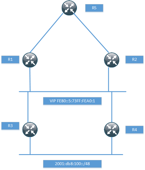
I have just setup enough of the topology to prove that it works with the next-hop, so I won’t be running any pings and so on. The routers R1 and R2 have a static route for the network behind R3 and R4.
ipv6 route 2001:DB8:100::/48 GigabitEthernet0/1 FE80::5:73FF:FEA0:1
When routing towards a link local address, the exit interface must be specified. R1 then runs BGP towards R5, notice that I’m not using next-hop-self.
router bgp 100
bgp router-id 1.1.1.1
bgp log-neighbor-changes
neighbor 2001:DB8:1::5 remote-as 100
!
address-family ipv6
redistribute static
neighbor 2001:DB8:1::5 activate
exit-address-family
If we look in the BGP RIB, we can see that the route is installed with a link local next-hop.
R1#sh bgp ipv6 uni
BGP table version is 2, local router ID is 1.1.1.1
Status codes: s suppressed, d damped, h history, * valid, > best, i - internal,
              r RIB-failure, S Stale, m multipath, b backup-path, f RT-Filter,
              x best-external, a additional-path, c RIB-compressed,
Origin codes: i - IGP, e - EGP, ? - incomplete
RPKI validation codes: V valid, I invalid, N Not found

     Network          Next Hop            Metric LocPrf Weight Path
 *>  2001:DB8:100::/48
                       FE80::5:73FF:FEA0:1
                                                0         32768 ?
What next-hop do we have at R5 though?
R5#sh bgp ipv6 uni
BGP table version is 10, local router ID is 5.5.5.5
Status codes: s suppressed, d damped, h history, * valid, > best, i - internal,
              r RIB-failure, S Stale, m multipath, b backup-path, f RT-Filter,
              x best-external, a additional-path, c RIB-compressed,
Origin codes: i - IGP, e - EGP, ? - incomplete
RPKI validation codes: V valid, I invalid, N Not found

     Network          Next Hop            Metric LocPrf Weight Path
 *>i 2001:DB8:100::/48
                       2001:DB8:1::1            0    100      0 ?
We see the next-hop of R1 and not the link local address. How did this happen? We aren’t using next-hop-self. If we debug at R1, we will see what happens.
R1#debug ip bgp updates
R1#debug ip bgp ipv6 uni
*Aug 30 06:19:15.863: BGP(1): 2001:DB8:1::5 NEXT_HOP part 1 net 2001:DB8:100::/48,
next FE80::5:73FF:FEA0:1
*Aug 30 06:19:15.863: BGP(1): Can't advertise 2001:DB8:100::/48 to 2001:DB8:1::5
with NEXT_HOP FE80::5:73FF:FEA0:1
*Aug 30 06:19:15.863: BGP(1): (base) 2001:DB8:1::5 send UPDATE (format)
2001:DB8:100::/48, next 2001:DB8:1::1, metric 0, path Local
We can see that BGP was going to advertise it with the link local next-hop but then realized that this would not work. It then replaced the link local next-hop with a global next-hop.
While it may have been true at some point that routes must point to a global next-hop, this does not hold true in modern code. BGP will automatically advertise its updates with a global next-hop.
More PIM-BiDir Considerations
Introduction
From my last post on PIM BiDir I got some great comments from my friend Peter Palúch. I still had some concepts that weren’t totally clear to me and I don’t like to leave unfinished business. There is also a lack of resources properly explaining the behavior of PIM BiDir. For that reason I would like to clarify some concepts and write some more about the potential gains of PIM BiDir is. First we must be clear on the terminology used in PIM BiDir.
Terminology
Rendezvous Point Address (RPA) – The RPA is an address that is used as the root of the distribution tree for a range of multicast groups. This address must be routable in the PIM domain but does not have to reside on a physical interface or device.
Rendezvous Point Link (RPL) – It is the physical link to which the RPA belongs. The RPL is the only link where DF election does not take place. The RFC also says “In BIDIR-PIM, all multicast traffic to groups mapping to a specific RPA is forwarded on the RPL of that RPA.” In some scenarios where the RPA is virtual, there may not be an RPL though.
Upstream – Traffic towards the root (RPA) of the tree. This is the direction used by packets traveling from source(s) to the RPL.
Downstream – Traffic going away from the root. The direction from which packets travel from the RPL to the receivers.
Designated Forwarder (DF) – A single DF exists for every RPA on a link, point to point or multipoint. The only exception as noted above is the RPL. The DF is the router with the best metric to the RPA. The DF is responsible for forwarding downstream traffic onto its link and forwarding upstream traffic from its link towards the RPL. The DF on a link is also responsible for processing Join messages from downstream routers on the link and ensuring packets are forwarded to local receivers as discovered by IGMP or MLD.
RPF Interface – The RPF interface is determined by looking up the RPA in the Multicast Routing Information Table (MRIB). The RPF information then determines which interface of the router that would be used to send packets towards the RPL of the group.
RPF Neighbor – The next node on the shortest path towards the RPA.
Sources in PIM BiDir
One of the confusing parts in PIM BiDir is how traffic travels from the source(s) to the RPA. There is no (S,G) and no PIM Register messages in PIM BiDir, so how is this handled?
When a source starts sending traffic it will send it towards the RPA regardless if there are any receivers or not. The DF on the segment is responsible for sending the traffic upstream towards the RPA. The packet then travels through the PIM domain until it reaches the root of the tree (RPA). In some articles on PIM BiDir, it is mentioned that there is no RPF check. This is not entirely true since RPF is used to find the right interface towards the RPA but it does not use RPF to ensure loop free forwarding, the DF mechanism is instead used for this.

The picture shows a source sending traffic to a multicast group, there are no interested receivers yet. Traffic from the source travels towards the RPA which is not a physical device but only exists virtually on a shared segment with the routers R1, R2 and R3. These routers are connected to the RPL and on the RPL, there is no DF election. This means that they are free to forward the packets, however, there are no receivers yet and hence no interfaces in the Outgoing Interface List (OIL). This means that traffic will simply get dropped in the bitbucket. This is a waste of bandwidth until at least one receiver joins the shared tree.
Considerations for PIM BiDir
Since there is no way to control what the multicast sources are sending, what we are giving up for getting minimal state in the PIM domain is bandwidth. It is not very likely though that a many-to-many multicast application will not have any receivers so this may be an acceptable sacrifice.
Due to having minimum state, PIM BiDir will use less memory compared to PIM ASM or PIM SSM, it will also use less CPU since there is less PIM messages to be generated and received and processed. Is this a consideration on modern platforms? It might be, it might not be. What is known though is that it is a less complex protocol than PIM ASM because it does not have a PIM Register process. Due to this, the RP, which does not even have to be a real router, can’t get overwhelmed by the unicast PIM Register messages. This also provides for an easier mechanism to provide RP redundancy compared to PIM ASM and SSM which requires anycast and MSDP to provide the same.
PIM BiDir Not Working in IOSv and CSR1000v
While writing this post I needed to run some tests, so I booted up VIRL and tested on IOSv but could not get PIM BiDir to work properly. I then tested with CSR1000v, both within VIRL and directly on an ESXi server with the same results. These images were quite new and it seems something is not working properly in them. When the routers were running in BiDir mode, they would not process the multicast and forward it on. Just a fair warning that if you try it that you may run into similar results, please share if you discover something interesting.
Putting it All Together
To get an understanding for the whole process, let us then describe all of the steps from when the source starts sending until the receiver starts receiving the traffic from the source.
The source starts sending traffic on the local segment to R4. R4 is the DF on the link since it’s the only router present.

R4 does a RPF check for 192.0.2.1 which is the RPA, through this process it finds the upstream interface and starts forwarding traffic towards the RPA where R1 is the RPF neighbor and the next router on the path towards the RPA.

R1 forwards traffic towards the RPA on its upstream interface but there are no interested receivers yet, so the traffic will get dropped in the bitbucket. Please note that both R2 and R3 does receive this traffic but if there is no interface in the OIL, the traffic simply gets dropped.

The PC then starts to generate an IGMP Report and sends it towards R5.

R5 is the DF on the segment which also means that it is the Designated Router (DR). It will generate a PIM Join (*,G) and send it towards the RPA on its upstream interface where R3 is the RPF neighbor. Only the DF and hence DR on a link may act on the IGMP Report.

R3 receives the PIM Join from R5 and since traffic is already being sent out by R1 on the RPL, R3 is allowed to start forwarding the traffic. Remember that there is no DF elected on the RPL. We now have end to end multicast flowing.

Conclusion
The main goal of this post was to show how the RP can be a virtual device on a shared segment. This means that redundancy can be designed into the RP role without any complex mechanisms used in PIM ASM. I also wanted to clarify some concepts with the forwarding and the terminology since there seem to be quite a few posts out there that are slightly wrong or not using the correct terminology.
Many to Many Multicast – PIM BiDir
Introduction
This post will describe PIM Bidir, why it is needed and the design considerations for using PIM BiDir. This post is focused on technology overview and design and will not contain any actual configurations.
Multicast Applications
Multicast is a technology that is mainly used for one-to-many and many-to-many applications. The following are examples of applications that use or can benefit from using multicast.
One-to-many
One-to-many applications have a single sender and multiple receivers. These are examples of applications in the one-to-many model.
Scheduled audio/video: IP-TV, radio, lectures
Push media: News headlines, weather updates, sports scores
File distributing and caching: Web site content or any file-based updates sent to distributed end-user or replicating/caching sites
Announcements: Network time, multicast session schedules
Monitoring: Stock prices, security system or other real-time monitoring applications
Many-to-many
Many-to-many applications have many senders and many receivers. One-to-many applications are unidirectional and many-to-many applications are bidirectional.
Multimedia conferencing: Audio/video and whiteboard is the classic conference application
Synchronized resources: Shared distributed databases of any type
Distance learning: One-to-many lecture but with “upstream” capability where receivers can question the lecturer
Multi-player games: Many multi-player games are distributed simulations and also have chat group capabilities.
Overview of PIM
PIM has different implimentations to be able to handle the above applications. There are mainly three implementatios of PIM, PIM Any Source Multicast (ASM), PIM Source Specific Multicast (SSM) and PIM BiDirectional (BiDir).
PIM ASM
PIM ASM was the first implementation and is well suited for one-to-many applications. ASM means that traffic from any source to a group will be delivered to the receiver(s). PIM ASM uses the concept of a Rendezvous Point Tree (RPT) and Shortest Path Tree (SPT). The RPT is a tree built from the receiver to a Rendezvous Point (RP). The tree from a multicast source to a receiver is called the SPT. Before the receiver can learn the source and build the SPT, the RP will have sent a PIM Join towards the source to build the SPT between the source and the RP. When looking in the mroute table, RPT state will be shown as (*,G) and SPT state will be shown as (S,G)

The responsibilities of the RP are:
- Receive PIM Register messages from the First Hop Router (FHR) and send Register Stop
- Join the SPT and the RPT so the receivers get traffic and find out the source of the multicast
Initially traffic flows through the RP, there is a more efficient path though. When the Last Hop Router (LHR) starts receiving the multicast it will switch over to the SPT.The SPT will be a more optimal path and (likely) introduce lower delay between the source and the receiver.

PIM ASM can support both one-to-many and many-to-many applications since it can use both SPT and RPT. To prevent LHR to switch to SPT, ip pim spt-threshold command can be used. It can either be set to switch over at a certain rate of traffic (kbps) or be set to infinity to always stay on the RPT. This can be combined with ACL to have certain groups always stay on the RPT and for others to switch over. PIM ASM can therefore use SPT for some groups and RPT for other groups. There are still drawbacks to PIM ASM, a few are mentioned here:
- Complex protocol state with Register messages
- Redundancy requires the use of MSDP
- Any source can send which opens attack vector for DoS and sending traffic from spoofed source
PIM SSM
PIM SSM was created to work better with one-to-many flows compared to PIM ASM. In PIM SSM, there is no complex handling of state and there is only SPT, no RPT. That also means that there is no need for a RP. PIM SSM is much easier to setup and use, it does require clients to support IGMPv3 so that the IGMP Report can contain which source the receiver wants to receive the traffic from. This also means that since there is no RP, there has to be some way for the receiver to know which sources send to which groups. This has to be hanled by some form of Out Of Band(OOB) mechanism. The most common use for SSM is IP-TV where the Set Top Box (STB) receives a list of sources and groups by contacting a server.
The drawback of PIM SSM is that (S,G) state is created requiring more memory. Depending on the number of sources, this may be a factor or not.
PIM BiDir
Bidirectional PIM was created to work better with many-to-many applications. PIM BiDir uses only RPT and no SPT. This means that there has to be a RP. With bidirectional PIM, the RP does not perform any of the functions of PIM ASM though, such as sending Register Stop messages or joining the SPT. Remember, in PIM BiDir, there is no SPT.The RP in PIM BiDir does not have to be a physical device since the RP is not performing any control plane functions. It is simply a way of forwarding traffic the right way, think of it as a vector. The RP can be a physical device and in that case it is a normal RP, just without the responsibilities of an RP as we know it in PIM ASM. When configuring PIM BiDir to have redundant RPs the RP is sometimes called Phantom RP, because it does not have to reside on a physical device.
PIM BiDir is often used in “hoot n holler” and financial applications. PIM BiDir and PIM SSM are at different ends of the spectrum where PIM ASM can serve both type of applications.
PIM uses the concept of Reverse Path Forwarding (RPF) to ensure loop free forwarding. RPF ensures that traffic comes in on the interface that would be used to send traffic out towards the source. PIM BiDir can send traffic both up and down the RPT. This is not normally supported by using RPF, to support this PIM BiDir uses a Designated Forwarder (DF) on each segment, even point-to-point segments. The main responsibility of the DF is to forward traffic upstream towards the RP. The DF is elected based on the metric towards the RP, essentially building a tree along the best path without having to install any (S,G) state. RPF is still used to find the appropiate path towards the Rendezvous Point Link (RPL) but it is the DF mechanism that ensures loop free forwarding.
RP Considerations
In PIM BiDir there isno MSDP, it does not use (S,G) so this is expected. To provide redundant RP in PIM BiDir, Phantom RP is used. The Phantom RP is a virtual RP which is not assigned to a physical device, it is often implemented by having two routers use a loopback with different subnet mask length.

Routers are assigned the RP adress of 192.0.2.1 which is then the Phantom RP, the actual routers where the traffic will flow through have been assigned 192.0.2.2 and 192.0.2.3 but with different net mask lengths. Normal best path rules will then forward traffic towards the longest path match which will be RP1 when it is available and RP2 when RP1 is not available. It is important to not configure the RP address as a physical interface address since this would break the redundancy. If a router was configured with the real address, it would not forward the traffic since the traffic would be destined for one of its own addresses.
Since the RP is so critical, redundancy must be provided. All traffic will pass through the RP which means that certain links in the network may have to carry a lot of the traffic. For this reason it can be necessary to have several RPs, that are acting as RPs for different multicast groups. The placement of the RP also becomes very important since traffic must flow through the RP.
PIM BiDir Considerations
PIM BiDir uses the DF mechanism and for the election to succeed, all the PIM routers on the segment must support PIM BiDir, otherwise the DF election will fail and PIM BiDir will not be supported on the segment. It is possible to have non PIM BiDir routers on a segment if a PIM neighbor filter is implemented to not form PIM adjacencies with certain routers. That way PIM BiDir can be gradually implemented into the network.
Closing Thoughts
PIM ASM supports all multicast models but at the cost of complexity. One could say that it’s a jack of all trades but does not excel at anything. PIM SSM is less complex and the best choice for one-to-many applications if the receivers have support for IGMPv3. PIM BiDir is best suited for many-to-many applications and keeps the least state of all the PIM implementations. Every PIM implementation has its use case and as an architect/designer its your job to know all the models and pick the best one based on business requirements.
Petition to Increase Cisco VIRL Node Limit
Cisco VIRL is a great tool but it is artificially limited to a maximum of 15 nodes today. I have created a petition to collect names to send to Cisco, to show that the community really wants to increase this limit to at least 30 nodes.
Please go sign the petition if you are interested in seeing VIRL get support for more than 15 nodes.
Interview with CCDE/CCAr Program Manager Elaine Lopes
I am currently studying for the CCDE exam. Elaine Lopes is the program manager for the CCDE and CCAr certification. I’ve had the pleasure of interacting with her online and meeting her at Cisco Live as well. The CCDE is a great certification and I wanted you to get some insight into the program and ask about the future of the CCDE. A big thanks to Elaine and Cisco for agreeing to do the interview.
Daniel: Hi Elaine, and welcome. It was nice seeing you at Cisco Live! Can you please give a brief introduction of yourself to the readers?
Elaine: Hi, it was nice to see you, too! My name is Elaine Lopes and I’m the CCDE and CCAr Certification Program Manager. I’ve been with Cisco’s Learning@Cisco team since 1999, – I’m passionate about how people’s lives can change for the better through education and certification.
Daniel: Elaine, why did Cisco create an expert level design program? What kind of people should be looking at the CCDE?
Elaine: Cisco has very well established expert-level certifications for network engineers in various fields which assess configuration, implementation, troubleshooting and operations skills; however, these certifications were never aimed to assess design skills. The root cause of many network failures is poor network design and the CCDE helps to fill this gap. The certification was created to assess a candidate’s skills in real-life network design. The candidate should mainly be able to meet business requirements through their network designs as well as understand design principles such as network resiliency, scalability and manageability! CCDE focuses on design by making technology decisions and justifying the choices made. Since CCDE is meant to assess design skills, it targets infrastructure network designers.
Daniel: Are there any prerequisites before taking the CCDE?
Elaine: There are no pre-requisites for the CCDE certification, although it is recommended that candidates have 7+ years of experience on network design in diverse environments.
Daniel: What kind of experience should a candidate have to be a good fit for the CCDE? What is the technology range that needs to be covered such as RS, SP, datacenter, security?
Elaine: CCDE is a role-based certification, and therefore it is desirable that candidates have experience (breadth and depth) in large-scale network designs, as they will be tested on making design decisions within constraints. CCDE focuses mainly on Layer 3 control plane, Layer 2 control plane and network virtualization technologies, but also assesses QoS, security, network management with a little of wireless, optical and storage technologies.
Daniel: Can you give us a short description of the exam process and at which locations the exam is available?
Elaine: The CCDE certification is divided into two steps. The first step is the CCDE written exam, which focuses on design aspects of the various technologies described above, and can be taken at any Pearson VUE testing center at any time. Once CCDE candidates pass the written exam, they then need to pass the CCDE practical exam, which is made of four different scenarios where technologies and design concepts are interconnected. The CCDE practical exam is tridimensional: the same technologies tested on the CCDE written exam plus the different job tasks (merge/divest, add technology, replace technology, scaling and design failure), and the task domains (analyze requirements, design, plan for the design deployment, and validate and optimize network designs). The CCDE practical exam is administered four days a year at any of the 275 Pearson Professional Centers (PPCs) worldwide.
Daniel: You are also responsible for the CCAr program. What is the difference between design and architecture? What kind of candidates should be looking at this exam?
Elaine: CCArs collaborate with senior leadership to create a vision for the network, and their outputs are the business and technical requirements which will be input for CCDEs to create a network design that meets these requirements. The pre-requisite for CCAr is to be a CCDE in good standing, with the target audience being the infrastructure architects who navigate between the technical and business worlds.
Daniel: What kind of study resources are available for the CCDE? I know you have been working hard on providing guidance in the written blueprint, what else is coming?
Elaine: The biggest challenge for CCDE candidates seems to be how to get started, so we recently launched the Streamlined Preparation Resources. This site offers a study methodology and links to many recordings with information about the CCDE program. It’s mainly a list of preparation resources that can be personalized for one’s own needs and offers diverse resource types in a very prescriptive way for CCDE candidates to prepare for the CCDE written exam, but also can be helpful for the practical exam. Since the CCDE practical exam is situation-based, the team decided to provide materials to make candidates think as network designers. The materials are not mapped 1:1 to the blueprint but our long-term objective will be to release the materials in bits and pieces as they come available.
Daniel: Elaine, tell us a bit about the upcoming CCDE study guide. Why was this book written and how should it be used to prepare for the CCDE?
Elaine: Marwan [Al-Shawi] approached me saying he wanted to author a CCDE book, so we had some conversations and exchanged many emails which helped shape the book outline, aiming to be an “all-in-one” study guide for the CCDE practical exam. He then went through the whole publishing process with Cisco Press. There are great technical reviewers involved in it, and the book is to be released soon – I can’t wait to get my copy!
Daniel: After my last blog post on the CCIE program, I received some comments where people questioned the integrity of the CCIE exam. How do you work with the integrity of the CCDE?
Elaine: Integrity has always been top of mind when considering the delivery of the CCDE practical exam: it’s Windows-based and administered at the secure PPCs. The exam changes between administrations, and the nature of the scenarios makes it hard to guess the responses.
Daniel: I know you have designed the CCDE to be as timeless and generic as possible while still covering the relevant technologies. How will the exam be affected of new technologies and forwarding paradigms, such as SDN?
Elaine: True. I’d expect the CCIEs and CCDEs out there to be at the forefront of adoption of these new technologies in the field, and we’re already making plans for incorporating these new technologies into the CCIE tracks. CCDE will be no different, but I don’t have details yet I can share.
Daniel: Creating exams is very difficult and people often have opinions on the material being tested. It’s not well known that you can comment on the exam while taking it. Isn’t it true that comments are one of your sources of feedback on the quality of the exam?
Elaine: I heavily rely on statistical analysis to understand both item and exam performance before making any adjustments to the exam.. To get a more holistic view, I also read the comments candidates make on items while taking the exam. These comments sometimes provide good insight on how to fix low-performing items.
Daniel: Elaine, how can people give feedback on the program outside of comments while taking the exam?
Elaine: Just send me an email elopes@cisco.com. To be informed on what’s going on in the CCDE world, you can connect with me on LinkedIn (Elaine Lopes) and/or Twitter (@elopes01).
Daniel: There is a Subject Matter Expert (SME) recruitment program for certifications within Cisco. Do you have SMEs for the CCDE and how can any CCDE’s out there contact Cisco if they want to be part of the SME program?
Elaine: SMEs are critical to assure the exams are relevant, so yes, I do have several CCDE certified SMEs participating on the various phases of the exam, from development teams to authoring/reviewing/editing items, to working on the preparation resources, to the maintenance of the existing exams, etc. If you are CCDE-certified and want to participate, join the program and I’ll contact you for the next opportunity to participate.
Daniel: Thank you so much for your time, Elaine! I hope we’ll meet soon again. Do you have any final words and where do you see the CCDE program going in the future?
Elaine: I wanted to give a hint to CCDE candidates taking the practical exam: take the time to read and connect with each scenario and don’t make decisions or assumptions outside the context of the scenario. If you read a question and the answer is not glaring, go back to the scenario materials! CCDE design principles don’t change, so when the time comes I see “sprinkling” design aspects of new technologies in the CCDE exams. Hope to see you soon!! It’s been a pleasure to participate, thank you for inviting me!
QoS Terminology – Comparing Cisco to MEF and RFC Terminology
Have you every thought that you knew a topic pretty well but then someone uses terminology that you aren’t used to? People that use Cisco a lot or live outside the MEF world use another terminology than people that are working on MEF certified networks. Even if we both know the concepts, if we don’t speak a common language it will be difficult to communicate and to the the right end result.
When I took the CCDE written at Cisco Live, some of the QoS related material felt a bit off to me. I feel quite confident with QoS so this took me by surprise. My theory is that some of the material was written by someone coming from another background and uses some wording that just felt a bit off to me. I thought that I would read through some of the MEF material to broaden my QoS horizon and see what other terms are being used. At the very least I will have learned something new.
If we start with the basics, we have flows in our networks and these flows have different needs regarding delay, jitter and packet loss. I will write different terms and I will indicate which belong to MEF terminology, the other terms will be related to what Cisco calls them or what they would be called in general outside of the MEF world.
Delay
Latency
Round Trip Time (RTT)
Frame Delay (MEF)
These all relate to how much delay that is acceptable in the network. It may be one-way or two-way requirements depending on the nature of the traffic. RTT always refers to the two-way delay.
Jitter
Frame Delay Variation (MEF)
The MEF term is actually a bit clearer here as jitter is the variation of delay.
Packet Loss
Frame Loss Ratio (MEF)
Once again, MEF term is a bit clearer because we are interested to see the packet loss as a ratio, such as 1/100 packets which we then use as a percentage for what is acceptable loss on a circuit.
Commited Burst (Bc)
Commited Burst Size (CBS)(MEF)
The Bc or CBS value is used to define how much traffic in bits or bytes can be sent during each time interval. Picking a too low value can lead to customer dropping a lot of packets and picking a too high value can lead to long time intervals which could affect high priority traffic. The formula Tc = Bc / CIR can be used for calculations.
Burst Excess (Be)
Excess Burst Size (EBS)(MEF)
Be or EBS is normally used to provide the customer a more “fair” use of a circuit by allowing them to send unused credits from one or more previous time intervals. This means that they can burst momentarily until they have used up the Bc + Be credits.
Committed Information Rate (CIR)
This is the rate that is guaranteed to the customer in the contract. The physical line rate could be 100 Mbit/s but the CIR is 50 Mbit/s. It should be noted that this is an average rate and that traffic is always sent at line rate which produces bursts of traffic. This means that the customer will for short periods of time send at above the CIR rate but on average they get CIR rate on the circuit.
Excess Information Rate (EIR)(MEF)
A provider/carrier may allow a customer to send at above CIR rate but only those packets that are within the CIR are guaranteed the performance characteristics as defined in the SLA. This is commonly implemented with a single rate Three Color Marker (srTCM) where packets that are within the CIR/CBS are marked as green, packets above CIR but within EIR/EBS are marked as yellow and packets that exceed the EIR/CBS are marked as red. Green packets are guaranteed performance as defined in the SLA, yellow packets get delivered according to best effort and red packets are dropped.
This illustration shows the concept of srTCM:

Peak Information Rate (PIR)
As noted by Faisal in the comments. PIR is not the same as EIR. PIR is actually CIR + EIR which means that we have two token buckets filling at the same time and incoming packets are checked against both to see if it matches CIR rate or EIR rate which will then set the color of the packet to be green or yellow. One example could be where customer has CIR of 10 Mbit/s and EIR of 10 Mbit/s which gives a combined rate (PIR) of 20 Mbit/s. The first 10 Mbit/s is guaranteed and the other 10 Mbit/s is sent through the provider network as long as there is capacity available.
This is a short post on different QoS terminology. Which terminology are you most used to?
Using BFD to Track WAN Status and Change HSRP Priority
It’s been five years since I started this blog! Time flies and a lot has happened since. Thanks for being along for the ride. What better way to celebrate than a blog post?
This post is going to be short and to the point.
Many of us run HSRP or VRRP. It is quite common to run it in a topology where you have dual routers and dual exits to the WAN and you don’t want to black hole your traffic.

One traditional way of achieving this is by tracking the interface that goes towards the WAN. There are a couple of drawbacks to this approach though:
- You may not get link down on failure (connecting to switch)
- You may experience an error that does not produce link down event
The next option is to use IP SLA that sends ICMP Echo towards the next-hop of the WAN or some destination further into the network. Ehanced Object Tracking (EOT) can then be used to create a track object that decrements the priority of the HSRP active router when the ICMP Echo probe fails. This works better but there are still some drawbacks to this approach:
- Frequency can’t be set to lower than one second
- There is no multiplier, one failed ping is enough which can lead to false positives
- False positives will lead to the state changing more than necessary
- The above can be solved by using a delay for the tracking object
- Using IP SLA is likely more CPU intensive than using BFD
Unfortunately there is no way to directly configure HSRP to check the status of BFD running on your WAN interface. That does not mean we can’t solve the task at hand though. BFD is supported over static routes. What if we insert a dummy route into the RIB when BFD is running successfully over the WAN link and track that this route is installed into the RIB. If it is not installed it must mean that BFD has failed and that the HSRP priority of the active router should be decremented.
The configuration is quite simple. In my lab I have an ISP router with the following config:
interface GigabitEthernet1.100
encapsulation dot1Q 100
ip address 10.0.0.1 255.255.255.252
bfd interval 500 min_rx 500 multiplier 3!
router bgp 1
bgp log-neighbor-changes
network 1.1.1.1 mask 255.255.255.255
neighbor 10.0.0.2 remote-as 2
neighbor 10.0.0.2 fall-over bfd
I’m using BGP in this case to have BFD packets sent over the link. There needs to be a protocol registered with BFD for the packets to be sent. It would be more likely for the ISP to configure a static route using BFD as well. If you are already running BGP, this configuration may be overkill since you could track routes coming from BGP.
This is then the configuration of the active HSRP router:
track 1 ip route 169.254.0.0 255.255.0.0 reachability
!
interface GigabitEthernet1
no ip address
negotiation auto
!
interface GigabitEthernet1.100
encapsulation dot1Q 100
ip address 10.0.0.2 255.255.255.252
bfd interval 500 min_rx 500 multiplier 3
!
interface GigabitEthernet1.200
encapsulation dot1Q 200
ip address 10.0.10.2 255.255.255.0
standby 1 ip 10.0.10.1
standby 1 priority 110
standby 1 preempt
standby 1 track 1 decrement 11
!
router bgp 2
bgp log-neighbor-changes
neighbor 10.0.0.1 remote-as 1
neighbor 10.0.0.1 fall-over bfd
!
ip route static bfd GigabitEthernet1.100 10.0.0.1
ip route 169.254.0.0 255.255.0.0 GigabitEthernet1.100 10.0.0.1
To trigger the BFD packets being sent over the WAN link we first have a static route pointing out the egress interface and the next-hop.
ip route static bfd GigabitEthernet1.100 10.0.0.1
Then we put a standard IP route statement which will insert the dummy route. It is important to point out the egress interface though for single-hop BFD.
ip route 169.254.0.0 255.255.0.0 GigabitEthernet1.100 10.0.0.1
EOT is used to track if the route is installed into the RIB or not.
track 1 ip route 169.254.0.0 255.255.0.0 reachability
The HSRP priority is decremented if the route is not in the RIB which will make the standby router become active.
standby 1 track 1 decrement 11
We can then test if it works by shutting down the interface on the ISP router.
ISP1(config)#int gi1
ISP1(config-if)#shut
ISP1(config-if)#
The change in the RIB is detected by the HSRP active router:
*Jul 29 15:57:23.278: %TRACK-6-STATE: 1 ip route 169.254.0.0/16 reachability Up -> Down
*Jul 29 15:57:24.872: %HSRP-5-STATECHANGE: GigabitEthernet1.200 Grp 1 state Active -> Speak
*Jul 29 15:57:36.582: %HSRP-5-STATECHANGE: GigabitEthernet1.200 Grp 1 state Speak -> Standby
The standby router takes over:
*Jul 29 15:57:24.872: %HSRP-5-STATECHANGE: GigabitEthernet1.200 Grp 1 state Standby -> Active
What are the advantages of this setup compared to IP SLA?
- Lightweight protocol designed to test reachability
- Can send packets faster than one second in between each
- Can define what multiplier to use
The drawback may be that you have to get your ISP to run BFD and that they need to put a static route in on their side as well. This can be a real route or a dummy route though.
Hopefully this post was somewhat useful and you’ll stay with me for another five years. Thanks for reading!
IPv6 Multicast
These are my notes for IPv6 multicast for the CCDE exam. Overview
- Prefix FF::/8 reserved for multicast
- Multicast Listener Discovery (MLD) replaces IGMP
- MLD is part of ICMPv6
- MLDv1 equivalent to IGMPv2
- MLDv2 equivalent to IGMPv3
- ASM, SSM and Bidir supported
- PIM identified by IPv6 next header 103
- BSR and static RP supported
- No support for MSDP
- Anycast supported through PIM, defined in RFC4610
- Any Source Multicast (ASM)
- PIM-SM, PIM-BiDir
- Default for generic multicast and unicast prefix-based multicast
- Starts with FF3x::/12
- Source Specific Multicast (SSM)
- PIM-SSM
- FF3X::/32 is allocated for SSM by IANA
- Currently prefix and plen is zero so FF3X::/96 is useable for SSM
- Embedded RP groups
- PIM-SM, PIM-BIDir
- Starts with FF70::/12
IPv6 Multicast Addressing
IPv6 multicast address format includes variable bits to define what type of address it is and what the scope is of the multicast group. The scope can be:
1 – Node
2 – Link
3 – Subnet
4 – Admin
5 – Site
8 – Organization
E – Global
The flags define if embedded RP is used, if the address is based on unicast and if the address is IANA assigned or not (temporary). The unicast based IPv6 multicast address allows an organization to create globally unique IPv6 multicast groups based on their unicast prefixes. This is similar to GLOP addressing in IPv4 but does not require an Autonomous System Number (ASN). IPv6 also allows for embedding the RP address into the multicast address itself. This provides a static RP to multicast group mapping mechanism and can be used to provide interdomain IPv6 multicast as there is no MSDP in IPv6. When using Ethernet, the destination MAC address of the frame will start with 33:33 and the remaining 32 bits will consist of the low order 32 bits of the IPv6 multicast address.
Well Known Multicast Addresses
FF02::1 – All Nodes
FF02::2 – All Routers
FF02::5 – OSPF All Routers
FF02::6 – OSPF DR Routers
FF02::A – EIGRP Routers
FF02::D – PIM Routers
Neighbor Solicitation and DAD
IPv6 also uses multicast to replace ARP through the neighbor solicitation process. To do this the solicited node multicast address is used and the prefix is FF02::1:FF/104 and the last 24 bits are taken from the lower 24 bits of the IPv6 unicast address. If Host A needs to get the MAC of Host B, Host A will send the NS to the solicited node multicast address of B. IPv6 also does Duplicate Address Detection (DAD) to check that noone else is using the same IPv6 address and this also uses the solicited node multicast address. If Host A is checking uniqueness of its IPv6 address, the message will be sent to the solicited node multicast address of Host A.
Multicast Listener Discovery (MLD)
- MLDv1 messages
- Listener Query
- Listener Report
- Listener Done
- MLDv2 messages
- Listener Query
- Listener Report
MLDv2 does not use a specific Done message which is equivalent to the Leave message in IGMP. It will stop sending Reports or send a Report which excludes the source it was previously interested in.
Protocol Independent Multicast (PIM) for IPv6
- PIM-SM (RP is required)
- Many to many applications (multiple sources, single group)
- Uses shared tree initially but may switch to source tree
- PIM-BiDir (RP is required)
- Bidirectional many to many applications (hosts can be sources and receivers)
- Only uses shared tree, less state
- PIM-SSM
- One to many applications (single source, single group)
- Always uses source tree
- Source must be learnt through out of band mechanism
Anycast RP
IPv6 does not have support for MSDP. It can support anycast RP through the use of PIM which can implement this feature. All the RPs doing anycast will use the same IPv6 address but they also require a unique IPv6 address that will be used to relay the PIM Register messages coming from the multicast sources. A RP-set is defined with the RPs that should be included in the Anycast RP and the PIM Register messages will be relayed to all the RPs defined in the RP-set. If the PIM Register message comes from an IPv6 address that is defined in the RP-set, the Register will not be sent along which is a form of split horizon to prevent looping of control plane messages. When a RP relays a PIM Register, this is done from a unique IPv6 address which is similar to how MSDP works.
Sources will find the RP based on the unicast metric as is normally done when implementing anycast RP. If a RP goes offline, messages will be routed to the next RP which now has the best metric.
Interdomain Multicast
These are my thoughts on interdomain multicast since there is no MSDP for IPv6. Embedded RP can be used which means that other organization needs to use your RP. Define a RP prefix that is used for interdomain multicast only or use a prefix that is used for internal usage but implement a data plane filter to filter out requests for groups that should not cross organizational boundaries. This could also be done by filtering on the the scope of the multicast address.
Another option would be to anycast RP with the other organization but this could get a lot messier unless a RP is defined for only a set of groups that are used for interdomain multicast. Each side would then have a RP defined for the groups and PIM Register messages would be relayed. The drawback would be that both sides could have sources but the policy may be that only one side should have sources and the other side only has listeners. This would be difficult to implement in a data plane filter. It might be possible to solve in the control plane by defining which sources the RP will allow to Register.
If using SSM, there is no need for a RP which makes it easier to implement interdomain multicast. There is always the consideration of joining two PIM domains but this could be solved by using static joins at the edge and implementing data plane filtering. Interdomain multicast is not something that is implemented a lot and it requires some thought to not merge into one failure domain and one administrative domain.
Final Thoughts
Multicast is used a lot in IPv6, multicast is more tightly integrated into the protocol than in IPv4, and it’s there even if you see it or not. The addressing, flags and scope can be a bit confusing at first but it allows for using multicast in a better way in IPv6 than in IPv4.
Service Provider IPv6 Deployment
These are my study notes regarding IPv6 deployment in SP networks in preparation for the CCDE exam.
Drivers for implementing IPv6
- External drivers
- SP customers that need access to IPv6 resources
- SP customers that need to interconnect their IPv6 sites
- SP customers that need to interface with their own customers over iPv6
- Internal drivers
- Handle problems that may be hard to fix with IPv4 such as large number of devices (cell phones, IP cameras, sensors etc)
- Public IPv4 address exhaustion
- Private IPv4 address exhaustion
- Strategic drivers
- Long term expansion plans and service offerings
- Preparing for new services and gaining competitive advantage
Infrastructure
- SP Core Infrastructure
- Native IPv4 core
- L2TPv3 for VPNs
- MPLS core
- MPLS VPNs
My reflection is that most cores would be MPLS enabled, however there are projects such as Terastream in Deutsche Telekom where the entire core is IPv6 enabled and L2TPv3 is used in place of MPLS.
- IPv6 in Native IPv4 Environments
- Tunnel v6 in v4
- Native v6 with dedicated resources
- Dual stack
The easiest way to get going with v6 was to tunnel it over v4. The next logical step was to enable v6 but on separate interfaces to not disturb the “real” traffic and to be able to experiment with the protocol. The end goal is dual stack, at least in a non MPLS enabled network.
- IPv6 in MPLS environments
- 6PE
- 6VPE
6PE is a technology to run IPv6 over an IPv4 enabled MPLS network. 6VPE does the same but with VRFs.
- Native IPv6 over Dedicated Data Link
- Dedicated data links between core routers
- Dedicated data links to IPv6 customers
- Connection to an IPv6 IX
- Dual stack
- All P + PE routers capable of v4 + v6 transport
- Either two IGPs or one IGP for both v4 + v6
- Requires more memory due to two routing tables
- IPv6 multicast natively supported
- All IPv6 traffic is routed in global space (no MPLS)
- Good for content distribution and global services (Internet)
- 6PE
- IPv6 global connectivity over an IPv4 MPLS core
- Transition mechanism (debatable)
- PEs are dual stacked and need 6PE configuration
- IPv6 reachability exchanged via MPBGP over iBGP sessions
- IPv6 packets transported from 6PE to 6PE inside MPLS
- The next-hop is an IPv4 mapped IPv6 address such as ::FFFF:1.1.1.1
- BGP label assigned for the IPv6 prefix
- Bottom label used due to P routers not v6 capable and for load sharing
- neighbor send-label is configured under BGP address-family ipv6
6PE is viewed as a transition mechanism but this is arguable, if you transport IPv4 over MPLS, you may want to do the same with IPv6 as well for consistency. Running 6PE means that there is fate sharing between v4 and v6 though, which could mean that an outage may affect both protocols. This could be avoided by running MPLS for IPv4 but v6 natively.
- Core network (P routers) left untouched
- IPv6 traffic inherits MPLS benefits such as fast-reroute and TE
- Incremental deployment possible (upgrade PE routers first)
- Each site can be v4-only, v4-VPN-only, v4+v6, v4-VPN+v6 and so on
- Scalability concerns due to separate RIB and FIB required per customer
- Mostly suitable for SPs with limited amount of PEs
- 6vPE
- Equivalent of VPNv4 but for IPv6
- Add VPNv6 address family under MPBGP
- Send extended communities for the prefixes under the address family
It is a common misconception for 6PE and 6vPE that traceroutes are not possible, that is however not entirely true. A P router can generate ICMPv6 messages that will follow the LSP to the egress PE and then the ICMPv6 error message is forwarded back to the originator of the traceroute.
- Route reflectors for 6PE and 6vPE
- Needed to scale BGP full mesh
- Dedicated RRs or data path RRs
- Either dedicated RR per AF or have multiple AFs per RR
- 6PE-RR must support IPv6 + label functionality
- 6vPE-RR must support IPv6 + label and extended communities functionality
PA vs PI
- PA advantages
- Aggregation towards upstreams
- Minimizes Internet routing table size
- PA disadvantages
- Customer is “locked” with the SP
- Renumbering can be painful
- Multi-homing and TE problems
The main driver here is if you are going to multi home or not. Renumbering is always painful but at least less so on IPv6 due to being able to advertise multiple IPv6 prefixes through Router Advertisements (RA).
- PI advantages
- Customers are not “locked” to the SP
- Multi homing is straight forward
- PI disadvantages
- Larger Internet routing table due to lack of efficient aggregation
- Memory and CPU needs on BGP speakers
Infrastructure Addressing (LLA vs global)
What type of addresses should be deployed on infrastructure links?
- Link Local Address FE80::/10
- Non routeable address
- Less attack surface
- Smaller routing tables
- Can converge faster due to smaller RIB/FIB
- Less need for iACL at edge of network
- Can’t ping links
- Can’t traceroute links
- May be more complex to manage with NMS
- Use global address on loopback for ICMPv6 messages
- Will not work with RSVP-TE tunnels
- Global only 2000::/3 (current IANA prefix)
- Globally routeable
- Larger attack surface unless prefix suppression is used
- Use uRPF and iACL at edge to protect your links
- Easier to manage
It would be interesting to hear if you have seen any deployments with LLA only on infrastructure links. In theory it’s a nice idea but it may corner you in some cases, preventing you from implementing other features that you wish to deploy in your network.
Use /126 or /127 on P2P links which is the equivalent of /30 or /31 on IPv4 links. For loopbacks use /128 prefixes. Always assign addresses from a range so that creating ACLs and iACLs becomes less tedious.
Using another prefix than /64 on an interface will break the following features:
- Neighbor Discovery (ND)
- Secure Neighbor Discovery (SEND)
- Privacy extensions
- PIM-SM with embedded RP
This is of course for segments where there are end users.
Prefix Allocation Practices
- Many SPs offer /48, /52, /56, /60 or /64 prefixes
- Enterprise customers receive one /48 or more
- Small business customers receive /52 or /56 prefix
- Broadband customers may receive /56 or /60 via DHCP Prefix Delegation (DHCP-PD)
Debating prefix allocation prefixes is like debating religion, politics or your favourite OS. Whatever you choose, make sure that you can revise your practice as future services and needs arrise.
Carrier Grade NAT(CGN)
- Short term solution to IPv4 exhaustage without changing Residential Gateway (RG) or SP infrastructure
- Subscriber uses NAT44 and SP does CGN with NAT44
- Multiplexes several customers onto the same public IPv4 address
- CGN performance and capabilities should be analysed in the planning phase
- May provide challenges in logging sessions
- Long term solution is to deploy IPv6
I really don’t like CGN, it slows down the deployment of IPv6. It’s a tool like anything else though that may be used selectively if there is no other solution available.
IPv6 over L2TP Softwires
- Dual stack IPv4/IPv6 on RG LAN side
- PPPoE or IPv4oE terminated on v4-only BNG
- L2TPv2 softwire between RG and IPv6-dedicated L2TP Network Server (LNS)
- Stateful architecture on LNS
- Offers dynamic control and granular accounting of IPv6 traffic
- Limited investment needed and limited impact on existing infrastructure
I have never seen IPv6 deployed over softwires, what about you readers?
6RD
- Uses 6RD CE (Customer Edge) and 6RD BR (Border Relay)
- Automatic prefix delegation on 6RD CE
- Stateless and automatic IPv6 in IPv4 encap and decap functions on 6RD
- Follows IPv4 routing
- 6RD BRs are adressed with IPv4 anycast for load sharing and resiliency
- Limited investment and impact on existing infrastructure
IPv4 via IPv6 Using DS-Lite with NAT44
- Network has migrated to IPv6 but needs to provide IPv4 services
- IPv4 packets are tunneled over IPv6
- Introduces two components: B4 (Basic Bridging Broadband Element) and AFTR (Address Family Transition Router)
- B4 typically sits in the RG
- AFTR is located in the core infrastructure
- Does not provide IPv4 and IPv6 hosts to talk to each other
- AFTR device terminates the tunnel and decapsulates IPv4 packet
- AFTR device performs NAT44 on customer private IP to public IP addresses
- Increased MTU, be aware of fragmentation
Connecting IPv6-only with IPv4-only (AFT64)
- Only applicable where IPv6-only hosts need to communicate with IPv4-only hosts
- Stateful or stateless v6 to v4 translation
- Includes NAT64 and DNS64
MAP (Mapping of Address and Port)
- MAP-T Stateless 464 translation
- MAP-E Stateless 464 encapsulation
- Allows sharing of IPv4 address across an IPv6 network
- Each shared IPv4 endpoint gets a unique TCP/UDP port range via “rules”
- All or part of the IPv4 address can be derived from the IPv6 prefix
- This allows for route summarization
- Need to allocate TCP/UDP port ranges to each CPE
- Stateless border relays in SP network
- Can be implemented in hardware for superior performance
- Can use anycast and have asymmetric routing
- No single point of failure
- Leverages IPv6 in the network
- No CGN inside SP network
- No need for logging or ALGs
- Dependent on CPE router
NAT64
- Stateful or stateless translation
- Stateful
- 1:N translation
- “PAT”
- TCP, UDP, ICMP
- Shares IPv4 addresses
- Stateless
- 1:1 translation
- “NAT”
- Any protocol
- No IPv4 address savings
DNS64 is often required in combination with NAT64 to send AAAA response to the IPv6-only hosts in case the server only exists in the v4 world.
464XLAT
- Somewhere around 15% of apps break with native v6 or NAT64
- Skype is one of these apps
- 464XLAT can help with most of these applications
- Handset does stateless 4 to 6 translation
- Network does NAT64
- Deployed by T-Mobile
Coming Updates to the CCIE Program
With everything going on in the industry, what is happening to the CCIE program?
I recently watched a webinar on coming updates to the CCIE program. I have also been talking to the CCIE and CCDE program managers which I am proud to call my friends. The certifications are a big part of Cisco’s business, people are afraid that certifications will lose value as Software Defined Networking (SDN) gains more traction in the industry. What is Cisco’s response to the ever changing landscape of networking?
We have already seen Cisco announce the CCNA cloud and CCNA industrial which shows that Cisco follows the market. Will we see a CCIE cloud or CCIE SDN? Doubtful… Why? Because SDN is not a track in itself, it will be part of all tracks… The CCIE DC will be refreshed to include topics like Application Centric Infrastructure (ACI) in the blueprint. When? It’s not official yet which means you have at least 6 months. My guess is that we will see an announcement before this year ends which would mean that the update is around a year away.
CCIE DC is the natural fit for SDN. What about the other tracks? Expect other tracks to get updated as well. The CCIE RS will add the Application Policy Infrastructure Controller Enterprise Module (APIC-EM) for sure and maybe some other topics as well. We will definitely see more of Intelligent WAN (IWAN) in the next update. The CCIE RS was recently bumped to version 5 so I would expect it to take a bit longer than the DC to refresh but it should not be that far out either. I think we can expect more refreshes since the networking is moving at a much faster pace now.
The CCIE SP will include topics such as Segment Routing (SR), Network Function Virtualizaiton (NFV), service chaining, Netconf and YANG and so on. At least that is what I expect. The CCIE SP recently moved to version 4 so I don’t expect it to change just yet but I’m sure Cisco is working on the next refresh already.
A change we have all been waiting to see is that Cisco is going to implement dual monitors in the CCIE lab. This has been discussed for a long time. According to Cisco only 6% of candidates have requested the dual monitors though which shows how important it is to give Cisco feedback. I’m sure more than 6% were bothered by the single screen in the lab. The delay in implementing it has been due to make sure that all lab centers get the same conditions at the same time to not create any debate about the testing environment.
Cisco is also working a lot with exam integrity, they have made changes to the lab delivery system in the backend to prevent people from leaking the material. There is also a much bigger pool of questions and topologies, a lot thanks to the virtualized environment. The Diagnostic (DIAG) section has also been successful in getting the passing rates down to the expected levels. Cisco does a lot of work with statistics to see how their material is received and what makes sense to ask about and if they need to rephrase something or remove it from the topology. They can also do statistical analysis to look for strange behavior from the candidates at the lab. Exam integrity is the #1 focus from my discussions with Cisco.
You have the chance to leave comments when you are taking an exam. I have been lazy in supplying comments in my tests which I will change from now on. From my discussions with the CCIE program managers this is very important feedback for them and their main source of information for how the test is being received.
If you are truly interested in improving the certifications of Cisco and you are already certified, you can apply to become a Subject Matter Expert (SME), SME’s help Cisco in exam development and in picking out the path of the certifications to include new topics and remove old ones.
I still believe in the CCIE program, it’s not going away. I think it would be a huge mistake for people to start diving into SDN without first getting the basic concepts straight. Everything can’t magically go into a fabric and never fail. Read some of Ivan Pepelnjak’s posts to get some perspective on large layer 2 domains. History always repeats itself.
