Design Considerations for North/South Flows in the Data Center
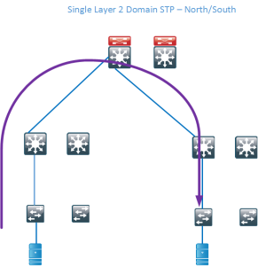
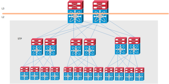
Traditional data centers have been built by using standard switches and running Spanning Tree (STP). STP blocks redundant links and builds a loop-free tree which is rooted at the STP root. This kind of topology wastes a lot of links which means that there is a decrease in bisectional bandwidth in the network. A traditional design may look like below where the blocking links have been marked with red color.
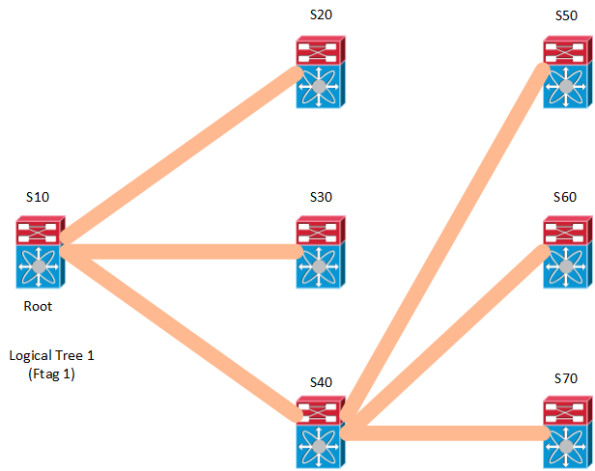
If we then remove the blocked links, the tree topology becomes very clear and you can see that there is only a single path between the servers. This wastes a lot of bandwidth and does not provide enough bisectional bandwidth. Bisectional bandwidth is the bandwidth that is available from the left half of the network to the right half of the network.
The traffic flow is highlighted below.
Technologies like FabricPath (FP) or TRILL can overcome these limitations by running ISIS and building loop-free topologies but not blocking any links. They can also take advantage of Equal Cost Multi Path (ECMP) paths to provide load sharing without doing any complex VLAN manipulations like with STP. A leaf and spine design is most commonly used to provide for a high amount of bisectional bandwidth.
Hot Standby Routing Protocol (HSRP) has been around for a long time providing First Hop Redundancy (FHR) in our networks. The drawback of HSRP is that there is only one active forwarder. So even if we run a layer 2 multipath network through FP, for routed traffic flows, there will only be one active path.
The reason for this is that FP advertsises its Switch ID (SID) and that the Virtual MAC (vMAC) will be available behind the FP switch that is the HSRP active device. Switched flows can still use all of the available bandwidth.
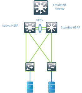
To overcome this, there is the possibility of running VPC+ between the switches and having the switches advertise an emulated SID, pretending to be one switch so that the vMAC will be available behind that SID.
There are some drawbacks to this however. It requires that you run VPC+ in the spine layer and you can still only have 2 active forwarders. if you have more spine devices they will not be uitilized for Nort/South flows. To overcome this there is a feature called Anycast HSRP.
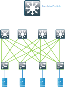
Anycast HSRP works in a similar way by advertising a virtual SID but it does not require links between the spines or VPC+. It also supports up to 4 active forwarders currently which provides for double the bandwidth compared to VPC+
Modern data centers provide for a lot more bandwidth and bisectional bandwidth than previous designs, but you still need to consider how routed flows can utilize the links in your network. This post should give you some insights on what to consider in such a scenario.
Introduction to Storage Networking and Design
Introduction
Storage and storage protocols are not generally well known by network engineers. Networking and storage have traditionally been two silos. Modern networks and data centers are looking to consolidate these two networks into one and to run them on a common transport such as Ethernet.
Hard Disks and Types of Storage
Hard disks can use different type of connectors and protocols.
- Advanced Technology Attachment (ATA)
- Serial ATA (SATA)
- Fibre Channel (FC)
- Small Computer System Interface (SCSI)
- Serial Attached SCSI (SAS)
ATA and SATA and SCSI are older standards, newer disks will typically use SATA or SAS where SAS is more geared towards the enterprise market. FC is used to attach to Storage Area Network (SAN)
Storage can either be file-level storage or block-level storage. File-level storage provides access to a file system through protocols such as Network File System (NFS) or Common Internet File System (CIFS). Block-level storage can be seen as raw storage that does not come with a file system. Block-level storage presents Logical Unit Number (LUN) to servers and the server may then format that raw storage with a file system. VmWare uses VmWare File System (VMFS) to format raw devices.
DAS, NAS and SAN
Storage can be accessed in different ways. Directly Attached Storage (DAS) is storage that is attached to a server, it may also be described as captive storage. There is no efficient sharing of storage and can be complex to implement and manage. To be able to share files the storage needs to be connected to the network. Network Attached Storage (NAS) enables the sharing of storage through the network and protocols such as NFS and CIFS. Internally SCSI and RAID will commonly be implemented. Storage Area Network (SAN) is a separate network that provides block-level storage as compared to the NAS that provides file-level storage.
Virtualization of Storage
Everything is being abstracted and virtualized these days, storage is no exception. The goal of anything being virtualized is to abstract from the physical layer and to provide a better utilization and less/no downtime when making changes to the storage system. It is also key in scaling since direct attached storage will not scale well. It also helps in decreasing the management complexity if multiple pools of storage can be accessed from one management tool. One basic form of virtualization is creating virtual disks that use a subset of the storage available on the physical device such as when creating a virtual machine in VmWare or with other hypervisors.
Virtualization exists at different levels such as block, disk, file system and file virtualization.
One form of file system virtualization is the concept of NAS where the storage is accessed through NFS or CIFS. The file system is shared among many hosts which may be running different operating systems such as Linux and Windows.
Block level storage can be virtualized through virtual disks. The goal of virtual disks is to make them flexible, being able to increase and decrease in size, provide as fast storage as needed and to increase the availability compared to physical disks.
There are also other forms of virtualization/abstracting where several LUNs can be hidden behind another LUN or where virtual LUNs are sliced from a physical LUN.
Storage Protocols
There are a number of protocols available for transporting storage traffic. Some of them are:
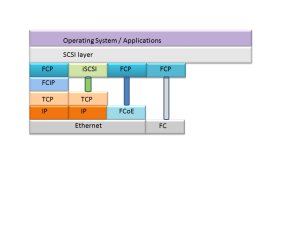
Internet Small Computer System Interface (iSCSI) – Transports SCSI requests over TCP/IP. Not suitable for high performance storage traffic
Fibre Channel Protocol (FCP) – It’s the interface protocol of SCSI on fibre channel
Fibre Channel over IP (FCIP) – A form of storage tunneling or FC tunneling where FC information is tunneled through the IP network. Encapsulates the FC block data and transports it through a TCP socket
Fibre Channel over Ethernet (FCoE) – Encapsulating FC information into Ethernet frames and transporting them on the Ethernet network
Fibre Channel
Fibre channel is a technology to attach to and transfer storage. FC requires lossless transfer of storage traffic which has been difficult/impossible to provide on traditional IP/Ethernet based networks. FC has provided more bandwidth traditionally than Ethernet, running at speeds such as 8 Gbit/s and 16 Gbit/s but Ethernet is starting to take over the bandwidth race with speeds of 10, 40, 100 or even 400 Gbit/s achievable now or in the near future.
There are a lot of terms in Fibre channel which are not familiar for us coming from the networking side. I will go through some of them here:
Host Bus Adapter (HBA) – A card with FC ports to connect to storage, the equivalent of a NIC
N_Port – Node port, a port on a FC host
F_Port – Fabric port, port on a switch
E_Port – Expansion port, port connecting two fibre channel switches and carrying frames for configuration and fabric management
TE_Port – Trunking E_Port, Cisco MDS switches use Enhanced Inter Switch Link (EISL) to carry these frames. VSANs are supported with TE_Ports, carrying traffic for several VSANs over one physical link
World Wide Name (WWN) – All FC devices have a unique identity called WWN which is similar to how all Ethernet cards have a MAC address. Each N_Port has its own WWN
World Wide Node Name (WWNN) – A globally unique identifier assigned to each FC node or device. For servers and hosts, the WWNN is unique for each HBA, if a server has two HBAs, it will have two WWNNs.
World Wide Port Number (WWPN) – A unique identifier for each FC port of any FC device. A server will have a WWPN for each port of the HBA. A switch has WWPN for each port of the switch.
Initiator – Clients called initiators issues SCSI commands to request services from logical units on a server that is known as a target
Fibre channel has many similarities to IP (TCP) when it comes to communicating.
- Point to point oriented – facilitated through device login
- Similar to TCP session establishment
- N_Port to N_Port connection – logical node connection point
- Similar to TCP/UDP sockets
- Flow controlled – hop by hop and end-to-end basis
- Similar to TCP flow control but a different mechanism where no drops are allowed
- Acknowledged – For certain types of traffic but not for others
- Similar to how TCP acknowledges segments
- Multiple connections allowed per device
- Similar to TCP/UDP sockets
Buffer to Buffer Credits
FC requires lossless transport and this is achieved through B2B credits.
- Source regulated flow control
- B2B credits used to ensure that FC transport is lossless
- The number of credits is negotiated between ports when the link is brought up
- The number of credits is decremented with each packet placed on the wire
- Does not rely on packet size
- If the number of credits is 0, transmission is stopped
- Number of credits incremented when “transfer ready” message received
- The number of B2B credits needs to be taken into consideration as bandwidth and/or distance increases
Virtual SAN (VSAN)
Virtual SANs allow to utilize the physical fabric better, essentially providing the same functionality as 802.1Q does to Ethernet.
- Virtual fabrics created from a larger cost-effective and redundant physical fabric
- Reduces waste of ports of a SAN island approach
- Fabric events are isolated per VSAN, allowing for higher availability and isolation
- FC features can be configured per VSAN, allowing for greater versability
Fabric Shortest Path First (FSPF)
To find the best path through the fabric, FSPF can be used. The concept should be very familiar if you know OSPF.
- FSPF routes traffic based on the destination Domain ID
- For FSPF a Domain ID identifies a VSAN in a single switch
- The number of maximum switches supported in a fabric is then limited to 239
- FSPF
- Performs hop-by-hop routing
- The total cost is calculated to find the least cost path
- Supports the use of equal cost load sharing over links
- Link costs can be manually adjusted to affect the shortest paths
- Uses Dijkstra algorithm
- Runs only on E_Ports or TE_Ports and provides loop free topology
- Runs on a per VSAN basis
Zoning
To provide security in the SAN, zoning can be implemented.
- Zones are a basic form of data path security
- A bidirectional ACL
- Zone members can only “see” and talk to other members of the zone. Similar to PVLAN community port
- Devices can be members of several zones
- By default, devices that are not members of a zone will be isolated from other devices
- Zones belong to a zoneset
- The zoneset must be active to enforce the zoning
- Only one active zoneset per fabric or per VSAN
SAN Drivers
What are the drivers for implementing a SAN?
- Lower Total Cost of Ownership (TCO)
- Consolidation of storage
- To provide better utilization of storage resources
- Provide a high availability
- Provide better manageability
Storage Design Principles
These are some of the important factors when designing a SAN:
- Plan a network that can handle the number of ports now and in the future
- Plan the network with a given end-to-end performance and throughput level in mind
- Don’t forget about physical requirements
- Connectivity to remote data centers may be needed to meet the business requirements of business continuity and disaster recovery
- Plan for an expected lifetime of the SAN and make sure the design can support the SAN for its expected lifetime
Device Oversubscription and Consolidation
- Most SAN designs will have oversubscription or fan-out from the storage devices to the hosts.
- Follow guidelines from the storage vendor to not oversubscribe the fabric too heavily.
- Consolidate the storage but be aware of the larger failure domain and fate sharing
- VSANs enable consolidation while still keeping separate failure domains
When consolidating storage, there is an increased risk that all of the storage or a large part of it can be brought offline if the fabric or storage controllers fail. Also be aware that when using virtualization techniques such as vSANS, there is fate sharing because several virtual topologies use the same physical links.
Convergence and Stability
- To support fast convergence, the number of switches in the fabric should not be too large
- Be aware of the number of parallell links, a lot of links will increase processing time and SPF run time
- Implement appropriate levels of redundancy in the network layer and in the SAN fabric
The above guidelines are very general but the key here is that providing too much redundancy may actually decrease the availability as the Mean Time to Repair (MTTR) increases in case of a failure. The more nodes and links in the fabric the larger the link state database gets and this will lead to SPF runs taking a longer period of time. The general rule is that two links is enough and that three is the maximum, anything more than that is overdoing it. The use of portchannels can help in achieving redundancy while keeping the number of logical links in check.
SAN Security
Security is always important but in the case of storage it can be very critical and regulated by PCI DSS, HIPAA, SOX or other standards. Having poor security on the storage may then not only get you fired but behind bars so security is key when designing a SAN. These are some recommendations for SAN security:
- Use secure role-based management with centralized authentication, authorization and logging of all the changes
- Centralized authentication should be used for the networking devices as well
- Only authorized devices should be able to connect to the network
- Traffic should be isolated and secured with access controls so that devices on the network can send and receive data securely while being protected from other activities of the network
- All data leaving the storage network should be encrypted to ensure business continuane
- Don’t forget about remote vaulting and backup
- Ensure the SAN and network passes any regulations such as PCI DSS, HIPAA, SOX etc
SAN Topologies
There are a few common designs in SANs depending on the size of the organization. We will discuss a few of them here and their characteristics and strong/weak points.
Collapsed Core Single Fabric
In the collapsed core, both the iniator and the target are connected through the same device. This means all traffic can be switched without using any Inter Switch Links (ISL). This provides for full non-blocking bandwidth and there should be no oversubscription. It’s a simple design to implement and support and it’s also easy to manage compared to more advanced designs.
The main concern of this design is how redundant the single switch is. Does it provided for redundant power, does it have a single fabric or an extra fabric for redundancy? Does the switch have redundant supervisors? At the end of the day, a single device may go belly up so you have to consider the time it would take to restore your fabric and if this downtime is acceptable compared to a design with more redundancy.
Collapsed Core Dual Fabric
The dual fabric designs removes the Single Point of Failure (SPoF) of the single switch design. Every host and storage device is connected to both fabrics so there is no need for an ISL. The ISL would only be useful in case the storage device loses its port towards fabric A and the server loses its port towards fabric B. This scenario may not be that likely though.
The drawback compared to the single fabric is the cost of getting two of every equipment to create the dual fabric design.
Core Edge Dual Fabric
For large scale SAN designs, the fabric is divided into a core and edge part where the storage is connected to the edge of the fabric. This design is dual fabric to provide high availability. The storage and servers are not connected to the same device, meaning that storage traffic must pass the ISL links between the core and the edge. The ISL links must be able to handle the load so that the oversubscription ratio is not too high.
The more devices that get added to a fabric, the more complex it gets and the more devices you have to manage. For a large design you may not have many options though.
Fibre Channel over Ethernet (FCoE)
Maintaining one network for storage and one for normal user data is costly and complex. It also means that you have a lot of devices to manage. Wouldn’t it be better if storage traffic could run on the normal network as well? That is where FCoE comes into play. The FC frames are encapsulated into Ethernet frames and can be sent on the Ethernet network. However, Ethernet isn’t lossless, is it? That is where Data Center Bridging (DCB) comes into play.
Data Center Bridging (DCB)
Ethernet is not a lossless protocol. Some devices may have support for the use of PAUSE frames but these frames would stop all communication, meaning your storage traffic would come to a halt as well. There was no way of pausing only a certain type of traffic. To provide lossless transfer of frames, new enhancements to Ethernet had to be added.
Priority Flow Control (PFC)
- PFC is defined in 802.1Qbb and provides PAUSE based on 802.p CoS
- When link is congested, CoS assigned to “no-drop” will be paused
- Other traffic assigned to other CoS values will continue to transmit and rely on upper layer protocols for retransmission
- PFC is not limited to FCoE traffic
It is also desirable to be able to guarantee traffic a certain amount of the bandwidth available and to not have a class of traffic use up all the bandwidth. This is where Enhanced Transmission Selection (ETS) has its use.
Enhanced Transmission Selection (ETS)
- Defined in 802.1Qaz and prevents a single traffic class from using all the bandwidth leading to starvation of other classes
- If a class does not fully use its share, that bandwidth can be used by other classes
- Helps to accomodate for classes that have a bursty nature
The concept is very similar to doing egress queuing through MQC on a Cisco router.
We now have support for lossless Ethernet but how can we tell if a device has implemented these features? Through the use of Data Center Bridging eXchange (DCBX).
Data Center Bridging Exchange (DCBX)
- DCBX is LLDP with new TLV fields
- Negotiates PFC, ETS, CoS values between DCB capable devices
- Simplifies management because parameters can be distributed between nodes
- Responsible for logical link up/down signaling of Ethernet and Fibre Channel
What is the goal of running FCoE? What are the drivers for running storage traffic on our normal networks?
Unified Fabric
Data centers require a lot of cabling, power and cooling. Because storage and servers have required separate networks, a lot of cabling has been used to build these networks. With a unified fabric, a lot of cabling can be removed and the storage traffic can use the regular IP/Ethernet network,so that half of the number of cables are needed. The following are some reasons for striving for a unified fabric:
- Reduced cabling
- Every server only requires 2xGE or 2x10GE instead of 2 Ethernet ports and 2 FC ports
- Fewer access layer switches
- A typical Top of Rack (ToR) design may have two switches for networking and two for storage, two switches can then be removed
- Fewer network adapters per server
- A Converged Network Adapter (CNA) combines networking and storage functionality so that half of the NICs can be removed
- Power and cooling savings
- Less NICs, mean less power which then also saves on cooling. The reduced cabling may also improve the airflow in the data center
- Management integration
- A single network infrastructure and less devices to manage decreases the overall management complexity
- Wire once
- There is no need to recable to provide network or storage connectivity to a server
Conclusion
This post is aimed at giving the network engineer an introduction into storage. Traditionally there have been silos between servers, storage and networking people but these roles are seeing a lot of more overlap in modern networks. We will see networks be built to provide both for data and storage traffic and to provide less complex storage. Protocols like iSCSI may get a larger share of the storage world in the future and FCoE may become larger as well.
Next Generation Multicast – NG-MVPN
Introduction
Multicast is a great technology that although it provides great benefits, is seldomly deployed. It’s a lot like IPv6 in that regard. Service providers or enterprises that run MPLS and want to provide multicast services have not been able to use MPLS to provide multicast Multicast has then typically been delivered by using Draft Rosen which is a mGRE technology to provide multicast. This post starts with a brief overview of Draft Rosen.
Draft Rosen
Draft Rosen uses GRE as an overlay protocol. That means that all multicast packets will be encapsulated inside GRE. A virtual LAN is emulated by having all PE routers in the VPN join a multicast group. This is known as the default Multicast Distribution Tree (MDT). The default MDT is used for PIM hello’s and other PIM signaling but also for data traffic. If the source sends a lot of traffic it is inefficient to use the default MDT and a data MDT can be created. The data MDT will only include PE’s that have receivers for the group in use.
Draft Rosen is fairly simple to deploy and works well but it has a few drawbacks. Let’s take a look at these:
- Overhead – GRE adds 24 bytes of overhead to the packet. Compared to MPLS which typically adds 8 or 12 bytes there is 100% or more of overhead added to each packet
- PIM in the core – Draft Rosen requires that PIM is enabled in the core because the PE’s must join the default and or data MDT which is done through PIM signaling. If PIM ASM is used in the core, an RP is needed as well. If PIM SSM is run in the core, no RP is needed.
- Core state – Unneccessary state is created in the core due to the PIM signaling from the PE’s. The core should have as little state as possible
- PIM adjacencies – The PE’s will become PIM neighbors with each other. If it’s a large VPN and a lot of PE’s, a lot of PIM adjacencies will be created. This will generate a lot of hello’s and other signaling which will add to the burden of the router
- Unicast vs multicast – Unicast forwarding uses MPLS, multicast uses GRE. This adds complexity and means that unicast is using a different forwarding mechanism than multicast, which is not the optimal solution
- Inefficency – The default MDT sends traffic to all PE’s in the VPN regardless if the PE has a receiver in the (*,G) or (S,G) for the group in use
Based on this list, it is clear that there is a room for improvement. The things we are looking to achieve with another solution is:
- Shared control plane with unicast
- Less protocols to manage in the core
- Shared forwarding plane with unicast
- Only use MPLS as encapsulation
- Fast Restoration (FRR)
NG-MVPN
To be able to build multicast Label Switched Paths (LSPs) we need to provide these labels in some way. There are three main options to provide these labels today:
- Multipoint LDP(mLDP)
- RSVP-TE P2MP
- Unicast MPLS + Ingress Replication(IR)
MLDP is an extension to the familiar Label Distribution Protocol (LDP). It supports both P2MP and MP2MP LSPs and is defined in RFC 6388.
RSVP-TE is an extension to the unicast RSVP-TE which some providers use today to build LSPs as opposed to LDP. It is defined in RFC 4875.
Unicast MPLS uses unicast and no additional signaling in the core. It does not use a multipoint LSP.
Multipoint LSP
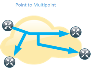
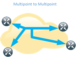
Normal unicast forwarding through MPLS uses a point to point LSP. This is not efficient for multicast. To overcome this, multipoint LSPs are used instead. There are two different types, point to multipoint and multipoint to multipoint.
- Replication of traffic in core
- Allows only the root of the P2MP LSP to inject packets into the tree
- If signaled with mLDP – Path based on IP routing
- If signaled with RSVP-TE – Constraint-based/explicit routing. RSVP-TE also supports admission control
- Replication of traffic in core
- Bidirectional
- All the leafs of the LSP can inject and receive packets from the LSP
- Signaled with mLDP
- Path based on IP routing
Core Tree Types
Depending on the number of sources and where the sources are located, different type of core trees can be used. If you are familiar with Draft Rosen, you may know of the default MDT and the data MDT.
Signalling the Labels
As mentioned previously there are three main ways of signalling the labels. We will start by looking at mLDP.
- LSPs are built from the leaf to the root
- Supports P2MP and MP2MP LSPs
- mLDP with MP2MP provides great scalability advantages for “any to any” topologies
- “any to any” communication applications:
- mVPN supporting bidirectional PIM
- mVPN Default MDT model
- If a provider does not want tree state per ingress PE source
- “any to any” communication applications:
- mLDP with MP2MP provides great scalability advantages for “any to any” topologies
- Supports Fast Reroute (FRR) via RSVP-TE unicast backup path
- No periodic signaling, reliable using TCP
- Control plane is P2MP or MP2MP
- Data plane is P2MP
- Scalable due to receiver driven tree building
- Supports MP2MP
- Does not support traffic engineering
RSVP-TE can be used as well with the following characteristics.
- LSPs are built from the head-end to the tail-end
- Supports only P2MP LSPs
- Supports traffic engineering
- Bandwidth reservation
- Explicit routing
- Fast Reroute (FRR)
- Signaling is periodic
- P2P technology at control plane
- Inherits P2P scaling limitations
- P2MP at the data plane
- Packet replication in the core
RSVP-TE will mostly be interesting for SPs that are already running RSVP-TE for unicast or for SPs involved in video delivery. The following table shows a comparision of the different protocols.
Assigning Flows to LSPs
After the LSPs have been signalled, we need to get traffic onto the LSPs. This can be done in several different ways.
- Static
- PIM
- RFC 6513
- BGP Customer Multicast (C-Mcast)
- RFC 6514
- Also describes Auto-Discovery
- mLDP inband signaling
- RFC 6826
Static
- Mostly applicable to RSVP-TE P2MP
- Static configuration of multicast flows per LSP
- Allows aggregation of multiple flows in a single LSP
PIM
- Dynamically assigns flows to an LSP by running PIM over the LSP
- Works over MP2MP and PPMP LSP types
- Mostly used but not limited to default MDT
- No changes needed to PIM
- Allows aggregation of multiple flows in a single LSP
BGP Auto-Discovery
- Auto-Discovery
- The process of discovering all the PE’s with members in a given mVPN
- Used to establish the MDT in the SP core
- Can also be used to discover set of PE’s interested in a given customer multicast group (to enable S-PSMSI creation)
- S-PMSI = Data MDT
- Used to advertise address of the originating PE and tunnel attribute information (which kind of tunnel)
BGP MVPN Address Family
- MPBGP extensions to support mVPN address family
- Used for advertisement of AD routes
- Used for advertisement of C-mcast routes (*,G) and (S,G)
- Two new extended communities
- VRF route import – Used to import mcast routes, similar to RT for unicast routes
- Source AS – Used for inter-AS mVPN
- New BGP attributes
- PMSI Tunnel Attribute (PTA) – Contains information about advertised tunnel
- PPMP label attribute – Upstream generated label used by the downstream clients to send unicast messages towards the source
- If mVPN address family is not used the address family ipv4 mdt must be used
BGP Customer Multicast
- BGP Customer Multicast (C-mcast) signalling on overlay
- Tail-end driven updates is not a natural fit for BGP
- BGP is more suited for one-to-many not many-to-one
- PIM is still the PE-CE protocol
- Easy to use with SSM
- Complex to understand and troubleshoot for ASM
MLDP Inband Signaling
- Multicast flow information encoded in the mLDP FEC
- Each customer mcast flow creates state on the core routers
- Scaling is the same as with default MDT with every C-(S,G) on a Data MDT
- IPv4 and IPv6 multicast in global or VPN context
- Typical for SSM or PIM sparse mode sources
- IPTV walled garden deployment
- RFC 6826
The natural choice is to stick with PIM unless you need very high scalability. Here is a comparison of PIM and BGP.
BGP C-Signaling
- With C-PIM signaling on default MDT models, data needs to be monitored
- On default/data tree to detect duplicate forwarders over MDT and to trigger the assert process
- On default MDT to perform SPT switchover (from (*,G) to (S,G))
- On default MDT models with C-BGP signaling
- There is only one forwarder on MDT
- There are no asserts
- The BGP type 5 routes are used for SPT switchover on PEs
- There is only one forwarder on MDT
- Type 4 leaf AD route used to track type 3 S-PMSI (Data MDT) routes
- Needed when RR is deployed
- If source PE sets leaf-info-required flag on type 3 routes, the receiver PE responds with with a type 4 route
Migration
If PIM is used in the core, this can be migrated to mLDP. PIM can also be migrated to BGP. This can be done per multicast source, per multicast group and per source ingress router. This means that migration can be done gradually so that not all core trees must be replaced at the same time.
It is also possible to have both mGRE and MPLS encapsulation in the network for different PE’s.
To summarize the different options for assigning flows to LSPs
- Static
- Mostly applicable to RSVP-TE
- PIM
- Well known, has been in use since mVPN introduction over GRE
- BGP A-D
- Useful where head-end assigns the flows to the LSP
- BGP C-mcast
- Alternative to PIM in mVPN context
- May be required in dual vendor networks
- MLDP inband signaling
- Method to stitch a PIM tree to a mLDP LSP without any additional signaling
Optimizing the MDT
There are some drawbacks with the normal operation of the MDT. The tree is signalled even if there is no customer traffic leading to unneccessary state in the core. To overcome these limitations there is a model called the partitioned MDT running over mLDP with the following characteristics.
- Dynamic version of default MDT model
- MDT is only built when customer traffic needs to be transported across the core
- It addresses issues with the default MDT model
- Optimizes deployments where sources are located in a few sites
- Supports anycast sources
- Default MDT would use PIM asserts
- Reduces the number of PIM neighbors
- PIM neighborship is unidirectional – The egress PE sees ingress PEs as PIM neighbors
Conclusion
There are many many different profiles supported, currently 27 profiles on Cisco equipment. Here are some guidelines to guide you in the selection of a profile for NG-MVPN.
- Label Switched Multicast (LSM) provides unified unicast and multicast forwarding
- Choosing a profile depends on the application and scalability/feature requirements
- MLDP is the natural and safe choice for general purpose
- Inband signalling is for walled garden deployments
- Partitioned MDT is most suitable if there are few sources/few sites
- P2MP TE is used for bandwidth reservation and video distribution (few source sites)
- Default MDT model is for anyone (else)
- PIM is still used as the PE-CE protocol towards the customer
- PIM or BGP can be used as an overlay protocol unless inband signaling or static mapping is used
- BGP is the natural choice for high scalability deployments
- BGP may be the natural choice if already using it for Auto-Discovery
- The beauty of NG-MVPN is that profile can be selected per customer/VPN
- Even per source, per group or per next-hop can be done with Routing Policy Language (RPL)
This post was heavily inspired and is basically a summary of the Cisco Live session BRKIPM-3017 mVPN Deployment Models by Ijsbrand Wijnands and Luc De Ghein. I recommend that you read it for more details and configuration of NG-MVPN.
My CLUS 2015 Schedule for San Diego
With roughly two months to go before Cisco Live starts, here is my preliminary schedule for San Diego.
I have two CCDE sessions booked to help me prepare for the CCDE exam. I have the written scheduled on wednesday and we’ll see how that goes.
I have a pretty strong focus on DC because I want to learn more in that area and that should also help me prepare for the CCDE.
I have the Routed Fast Convergence because it’s a good session and Denise Fishburne is an amazing instructor and person.
Are you going? Do you have any sessions in common? Please say hi if we meet in San Diego.
OSPF Design Considerations
Introduction
Open Shortest Path First (OSPF) is a link state protocol that has been around for a long time. It is geneally well understood, but design considerations often focus on the maximum number of routers in an area. What other design considerations are important for OSPF? What can we do to build a scalable network with OSPF as the Interior Gateway Protocol (IGP)?
Prefix Suppression
The main goal of any IGP is to be stable, converge quickly and to provide loop free connectivity. OSPF is a link state protocol and all routers within an area maintain an identical Link State Data Base (LSDB). How the LSDB is built it out of scope for this post but one relevant factor is that OSPF by default advertises stub links for all the OSPF enabled interfaces. This means that every router running OSPF installs these transit links into the routing table. In most networks these routes are not needed, only connectivity between loopbacks is needed because peering is setup between the loopbacks. What is the drawback of this default behavior?
- Larger LSDB
- SPF run time increased
- Growth of the routing table
To change this behavior, there is a feature called prefix suppression. When this feature is enabled the stub links are no longer advertised. The benefits of using prefix suppression is:
- Smaller LSDB
- Shorter SPF run time
- Faster convergence
- Remote attack vector decreased
If there needs to be connectivity to these prefixes for the sake of monitoring or other reasons, these prefixes can be carried in BGP.
How Many Routers in an Area?
The most common question is “How many routers in an Area?”. As usual, the answer is, it depends… In the past the hardware of routers such as the CPU and memory severely limited the scalability of an IGP but these are not much of an factor on modern devices. So what factors decide how many routers can be deployed in an area?
- Number of adjacent neighbors
- How much information is flooded in the area? How many LSAs are in the area?
- Keep router LSA under MTU size
– Implies lots of interfaces (and possibly lots of neighbors)
– Exceeding the MTU leeds to IP fragmentation which should be avoided
It’s impossible to give an exact answer to how many routers that fit into an area. There are ISPs out there running hundreds or even thousands in the same area. Doing so creates a very large failure domain though, a misbehaving router or link will cause all routers in the area to run SPF. To create a smaller failure domain, areas could be used, on the other hand MPLS does not play well with areas… So it depends…That is also why we see technologies like BGP-LS where you can have IGP islands glued together by BGP.
How many ABRs in an Area?
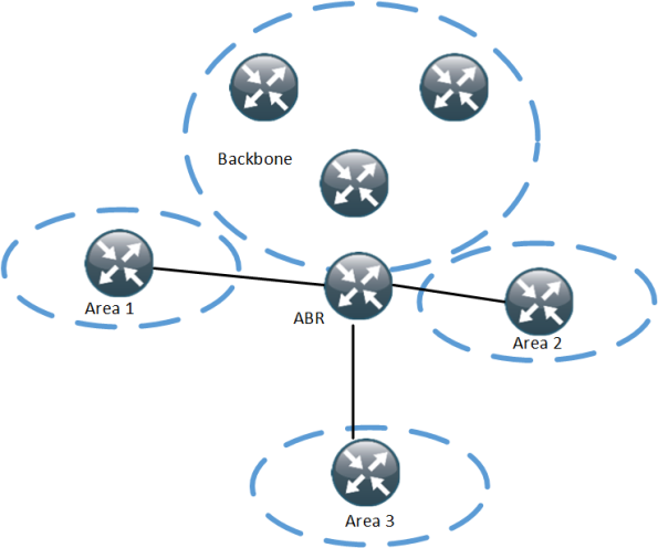
How many ABRs are suitable in an area? The ABR is very critical in OSPF due to the distance vector behavior between areas in OSPF. Traffic must pass through the ABR. Having one ABR may not be enough but adding too many adds complexity and adds flooding of LSAs and increases the size of the LSDB.
- More ABRs create more Type 3 LSA replication within the backbone and in other areas
- This can create scalability issues in large scale routing
- 10 prefixes in area 0 and 10 prefixes in area 1 would generate 60 summary LSAs with just 3 ABRs
- Increasing the number of areas or the number of ABRs would worsen the situation
How Many Areas per ABR?
Based on what we learned above, increasing the number of areas on an ABR quickly adds up to a lot of LSAs.
This ABR is in four areas, if every area contains 10 prefixes, the ABR has to generate 120 Type 3 summary LSAs in total.
- More areas per ABR puts more burden on the ABR
- More type 3 LSAs will be generated by the ABR
- Increasing the number of areas will worsen the situation
Considerations for Intra-Area Routing Scalability
To build a stable and scalable intra-area network, take the following parameters into consideration:
- Physical link flaps can cause instability in OSPF
– Consider using IP dampening - Avoid having physical links in OSPF through the use of prefix suppression
- BGP can be used to carry transit links for monitoring purpose
Considerations for Inter-Area Routing Scalability
- Filter physical links outside the area through type 3 filtering feature
- Every area should only carry loopback addresses for all routers
- NMS station may keep track of physical links if needed
- These can be redistributed into BGP
OSPF Border Connections
OSPF always prefers intra-area paths to inter-area paths, regardless of metric. This may cause suboptimal routing under certain conditions.
- Assume the link between D and E is in area 0
- If the link between D and F fails, traffic will follow the intra area path D -> G, G -> E and E -> F
This could be solved by adding an extra interface/subinterface between D and E in area 1. This would increase the number of LSAs though…
OSPF Hub and Spoke
- Make spoke areas as stubby as possible
– If possible, make the area totally stubby
– If redistribution is needed, make the area totally not-so-stubby - Be aware of reachability issues, make sure hub router becomes DR and use network type of Point to Multipoint (P2MP) if needed
– P2MP has smaller DB size compared to Point to Point (P2P)
– P2P will use more address space and increase the DB size compared to P2MP but it may be beneficial for other reasons when trying to achieve fast convergence - If the number of spokes is small, the hub and spokes can be placed within an area such as the backbone
- If the number of spokes is large, make the hub an ABR and split off the spokes in area(s)
Summary
OSPF is a link state protocol that can scale to large networks if the network is designed according to the characteristics of OSPF. This post described design considerations and features such as prefix suppression that will help in scaling OSPF. For a deeper look at OSPF design, go through BRKRST-2337, available at Cisco Live 365.
A Quick Look at Cisco FabricPath
Cisco FabricPath is a proprietary protocol that uses ISIS to populate a “routing table” that is used for layer 2 forwarding.
Whether we like or not, there is often a need for layer 2 in the Datacenter for the following reasons:
- Some applications or protocols require to be layer 2 adjacent
- It allows for virtual machine/workload mobility
- Systems administrators are more familiar with switching than routing
A traditional network with layer 2 and Spanning Tree (STP) has a lot of limitations that makes it less than optimal for a Datacenter:
- Local problems have a network-wide impact
- The tree topology provides limited bandwidth
- The tree topology also introduces suboptimal paths
- MAC address tables don’t scale
In the traditional network, because STP is running, a tree topology is built. This works better for for flows that are North to South, meaning that traffic passes from the Access layer, up to Distribution, to the Core and then down to Distribution and to the Access layer again. This puts a lot of strain on Core interconnects and is not well suited for East-West traffic which is the name for server to server traffic.
A traditional Datacenter design will look something like this:
If we want end-to-end L2, we could build a network like this:
What would be the implications of building such a network though?
- Large failure domain
- Unknown unicast and broadcast flooding through large parts of the network
- A large number of STP instances needed unless using MST
- Topology change will have a large impact on the network and may cause flooding
- Large MAC address tables
- Difficult to troubleshoot
- A very brittle network
So let’s agree that we don’t want to build a network like this. What other options do we have if we still need layer 2? One of the options is Cisco FabricPath.
FabricPath provides the following benefits:
- Reduction/elimination of STP
- Better stability and convergence characteristics
- Simplified configuration
- Leverage parallell paths
- Deterministic throughput and latency using typical designs
- “VLAN anywhere” flexibility
The FabricPath control plane consists of the following elements:
- Routing table – Uses ISIS to learn Switch IDS (SIDs) and build a routing table
- Multidestination trees – Elects roots and builds multidestination trees
- Mroute table – IGMP snooping learns group membership at the edge, Group Member LSPs (GM-LSPs) are flooded by ISIS into the fabric
Observe that LSPs has nothing to do with MPLS in this case and that this is not MAC based routing, routing is based on SIDs.
FabricPath ISIS learns the shortest path to each SID based on link metrics/path cost. Up to 16 equal (ECMP) routes can be installed. Choosing a path is based on a hashing function using Src IP/Dst IP/L4/VLAN which should be good for avoiding polarization.
FabricPath supports multidestination trees with the following capabilities:
- Multidestination traffic is contained to a tree topology, a network-wide identifier (Ftag) is assigned to each tree
- A root switch is elected for each multidestination tree
- Multipathing is supported through multiple trees
Note that root here has nothing to do with STP, think of it in terms of multicast routing.
Multidestination trees do not dictate forwarding for unicast, only for multidestination packets.
The FabricPath data plane behaves according to the following forwarding rules:
- MAC table – Hardware performs MAC lookup at CE/FabricPath edge only
- Switch table – Hardware performs destination SID lookups to forward unicast frames to other switches
- Multidestination table – A hashing function selects the tree, multidestination table identifies on which interfaces to flood based on selected tree
The Ftag used in FabricPath identifies which ISIS topology to use for unicast packets and for multidestination packets, which tree to use.
If a FabricPath switch belongs to a topology, all VLANs of that topology should be configured on that switch to avoid blackholing issues.
FabricPath supports 802.1p but can also match/set DSCP and match on other L2/L3/L4 information.
With FabricPath, edge switches only need to learn:
- Locally connected host MACs
- MACs with which those hosts are bidirectionally communicating
This reduces the MAC address table capacity requirements on Edge switches.
FabricPath Designs
There are different designs that can be used together with FabricPath. The first one is routing at the Aggregation layer.
The first design is the most classic one where STP has been replaced by FP in the Access layer and routing is used above the Aggregation layer.
This design has the following characteristics:
- Evolution of current design practices
- The Aggregation layer functions as FabricPath spine and L2/L3 boundary
– FabricPath switching for East – West intra VLAN traffic
– SVIs for East – West inter VLAN traffic
– Routed uplinks for North – South routed flows - Access layer provides pure L2 functions
– FabricPath core ports facing Aggregation layer
– CE edge ports facing hosts
– Optionally vPC+ can be used for active/active host connections
This design is the simplest option and is an extension of regular Access/Aggregation designs. It provides the following benefits:
- Simplified configuration
- Removal of STP
- Traffic distribution over all uplinks without the use of vPC
- Active/active gateways
- “VLAN anywhere” at the Access layer
- Topological flexibility
– Direct-path forwarding option
– Easily provision additional AccessAggregation bandwidth
– Easily deploy L4-L7 services
– Can use vPC+ towards legacy Access switches
There is also the centralized routing design which looks like the following:
Centralized routing has the following characteristics:
- Traditional Aggregation layer becomes pure FabricPath spine
– Provides uniform any-to-any connectivity between leaf switches
– In simplest case, only FabricPath switching occurs in spine
– Optionally, some CE edge ports exist to provide external router connections - FabricPath leaf switches, connecting to spine, have specific “personality”
– Most of the leaf switches will provide server connectivity, like traditional access switches in “Routing at Aggregation” designs
– Two or more leaf switches provide L2/L3 boundary, inter-VLAN routing and North-South routing
– Other or same leaf switches may provide L4-L7 services - Decouples L2/L3 boundary and L4-L7 services provisioning from Spine
– Simplifies Spine design
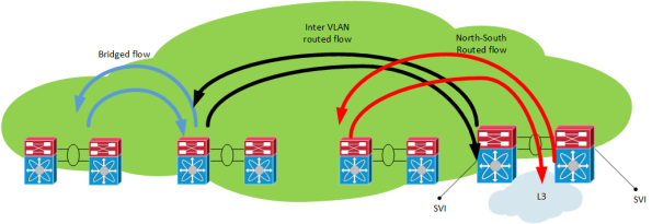
The different traffic flows in this design looks like the following:
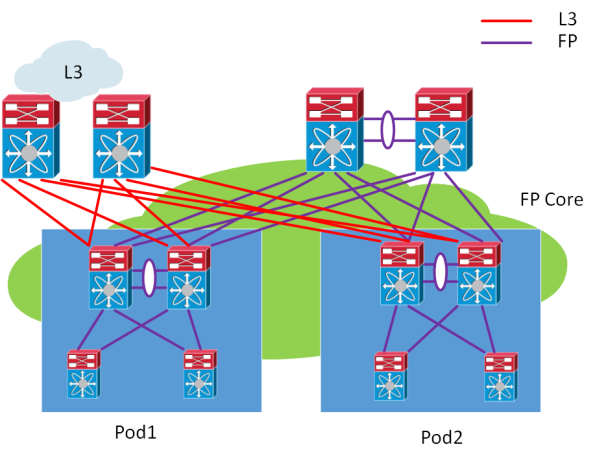
Another design is the multi-pod design which can look like the following:
The multi-pod design has the following characteristics:
- Allows for more elegant DC-wide versus pod-local VLAN definition/isolation
– No need for pod-local VLANs to exist in core
– Can support VLAN id reuse in multiple pods - Define FabricPath VLANs -> map VLANs to topology -> map topology to FabricPath core port(s)
- Default topology always includes all FabricPath core ports
– Map DC-wide VLANs to default topology - Pod-local core ports also mapped to pod-local topology
– Map pod-local VLANs to pod-local topology
This post briefly describes Cisco FabricPath which is a technology for building scalable L2 topologies, allowing for more bisectional bandwidth to support East-West flows which are common in Datacenters. To dive deeper into FabricPath, visit the Cisco Live website.
CLUS Keynote Speaker – It’s a Dirty Job but Somebody’s Gotta Do It
Did you guess by the title who will be the celebrity keynote speaker for CLUS San Diego? It’s none other than Mike Rowe, also known as the dirtiest man on TV.
Mike is the man behind “Dirty Jobs” on the Discovery Channel. Little did he know when pitching the idea to Discovery that they would order 39 episodes of it. Mike traveled through 50 states and completed 300 different jobs going through swamps, sewers, oil derricks, lumberjack camps and what not.
Mike is also a narrator and can be heard in “American Chopper”, “American Hot Rod”, “Deadliest Catch”, “How the Universe Works” and other TV shows.
He is also a public speaker and often hired by Fortune 500 companies to tell their employees frightening stories of maggot farmers and sheep castrators.
Mike also believes in skilled trades and in working smart AND hard. He has written extensively on the country’s relationship with work and the skill gap.
I’m sure Mike’s speach will be very interesting…and maybe a bit gross…
The following two links take you to Cisco Live main page and the registration packages:
HSRP AWARE PIM
In environments that require redundancy towards clients, HSRP will normally be running. HSRP is a proven protocol and it works but how do we handle when we have clients that need multicast? What triggers multicast to converge when the Active Router (AR) goes down? The following topology is used:
One thing to notice here is that R3 is the PIM DR even though R2 is the HSRP AR. The network has been setup with OSPF, PIM and R1 is the RP. Both R2 and R3 will receive IGMP reports but only R3 will send PIM Join, due to it being the PIM DR. R3 builds the (*,G) towards the RP:
R3#sh ip mroute 239.0.0.1
IP Multicast Routing Table
Flags: D - Dense, S - Sparse, B - Bidir Group, s - SSM Group, C - Connected,
       L - Local, P - Pruned, R - RP-bit set, F - Register flag,
       T - SPT-bit set, J - Join SPT, M - MSDP created entry, E - Extranet,
       X - Proxy Join Timer Running, A - Candidate for MSDP Advertisement,
       U - URD, I - Received Source Specific Host Report,
       Z - Multicast Tunnel, z - MDT-data group sender,
       Y - Joined MDT-data group, y - Sending to MDT-data group,
       G - Received BGP C-Mroute, g - Sent BGP C-Mroute,
       N - Received BGP Shared-Tree Prune, n - BGP C-Mroute suppressed,
       Q - Received BGP S-A Route, q - Sent BGP S-A Route,
       V - RD & Vector, v - Vector, p - PIM Joins on route
Outgoing interface flags: H - Hardware switched, A - Assert winner, p - PIM Join
 Timers: Uptime/Expires
 Interface state: Interface, Next-Hop or VCD, State/Mode

(*, 239.0.0.1), 02:54:15/00:02:20, RP 1.1.1.1, flags: SJC
  Incoming interface: Ethernet0/0, RPF nbr 13.13.13.1
  Outgoing interface list:
    Ethernet0/2, Forward/Sparse, 00:25:59/00:02:20
We then ping 239.0.0.1 from the multicast source to build the (S,G):
S1#ping 239.0.0.1 re 3
Type escape sequence to abort.
Sending 3, 100-byte ICMP Echos to 239.0.0.1, timeout is 2 seconds:

Reply to request 0 from 10.0.0.10, 35 ms
Reply to request 1 from 10.0.0.10, 1 ms
Reply to request 2 from 10.0.0.10, 2 ms
The (S,G) has been built:
R3#sh ip mroute 239.0.0.1
IP Multicast Routing Table
Flags: D - Dense, S - Sparse, B - Bidir Group, s - SSM Group, C - Connected,
       L - Local, P - Pruned, R - RP-bit set, F - Register flag,
       T - SPT-bit set, J - Join SPT, M - MSDP created entry, E - Extranet,
       X - Proxy Join Timer Running, A - Candidate for MSDP Advertisement,
       U - URD, I - Received Source Specific Host Report,
       Z - Multicast Tunnel, z - MDT-data group sender,
       Y - Joined MDT-data group, y - Sending to MDT-data group,
       G - Received BGP C-Mroute, g - Sent BGP C-Mroute,
       N - Received BGP Shared-Tree Prune, n - BGP C-Mroute suppressed,
       Q - Received BGP S-A Route, q - Sent BGP S-A Route,
       V - RD & Vector, v - Vector, p - PIM Joins on route
Outgoing interface flags: H - Hardware switched, A - Assert winner, p - PIM Join
 Timers: Uptime/Expires
 Interface state: Interface, Next-Hop or VCD, State/Mode

(*, 239.0.0.1), 02:57:14/stopped, RP 1.1.1.1, flags: SJC
  Incoming interface: Ethernet0/0, RPF nbr 13.13.13.1
  Outgoing interface list:
    Ethernet0/2, Forward/Sparse, 00:28:58/00:02:50

(41.41.41.10, 239.0.0.1), 00:02:03/00:00:56, flags: JT
  Incoming interface: Ethernet0/0, RPF nbr 13.13.13.1
  Outgoing interface list:
    Ethernet0/2, Forward/Sparse, 00:02:03/00:02:50
The unicast and multicast topology is not currently congruent, this may or may not be important. What happens when R3 fails?
R3(config)#int e0/2
R3(config-if)#sh
R3(config-if)#
No replies to the pings coming in until PIM on R2 detects that R3 is gone and takes over the DR role, this will take between 60 to 90 seconds with the default timers in use.
S1#ping 239.0.0.1 re 100 ti 1
Type escape sequence to abort.
Sending 100, 100-byte ICMP Echos to 239.0.0.1, timeout is 1 seconds:

Reply to request 0 from 10.0.0.10, 18 ms
Reply to request 1 from 10.0.0.10, 2 ms....................................................................
.......
Reply to request 77 from 10.0.0.10, 10 ms
Reply to request 78 from 10.0.0.10, 1 ms
Reply to request 79 from 10.0.0.10, 1 ms
Reply to request 80 from 10.0.0.10, 1 ms
We can increase the DR priority on R2 to make it become the DR.
R2(config-if)#ip pim dr-priority 50
*Feb 13 12:42:45.900: %PIM-5-DRCHG: DR change from neighbor 10.0.0.3 to 10.0.0.2 on interface Ethernet0/2
HSRP aware PIM is a feature that started appearing in IOS 15.3(1)T and makes the HSRP AR become the PIM DR. It will also send PIM messages from the virtual IP which is useful in situations where you have a router with a static route towards an Virtual IP (VIP). This is how Cisco describes the feature:
HSRP Aware PIM enables multicast traffic to be forwarded through the HSRP active router (AR), allowing PIM to leverage HSRP redundancy, avoid potential duplicate traffic, and enable failover, depending on the HSRP states in the device. The PIM designated router (DR) runs on the same gateway as the HSRP AR and maintains mroute states.
In my topology, I am running HSRP towards the clients, so even though this feature sounds as a perfect fit it will not help me in converging my multicast. Let’s configure this feature on R2:
R2(config-if)#ip pim redundancy HSRP1 hsrp dr-priority 100
R2(config-if)#
*Feb 13 12:48:20.024: %PIM-5-DRCHG: DR change from neighbor 10.0.0.3 to 10.0.0.2 on interface Ethernet0/2
R2 is now the PIM DR, R3 will now see two PIM neighbors on interface E0/2:
R3#sh ip pim nei e0/2
PIM Neighbor Table
Mode: B - Bidir Capable, DR - Designated Router, N - Default DR Priority,
      P - Proxy Capable, S - State Refresh Capable, G - GenID Capable
Neighbor          Interface                Uptime/Expires    Ver   DR
Address                                                            Prio/Mode
10.0.0.1          Ethernet0/2              00:00:51/00:01:23 v2    0 / S P G
10.0.0.2          Ethernet0/2              00:07:24/00:01:23 v2    100/ DR S P G
R2 now has the (S,G) and we can see that it was the Assert winner because R3 was previously sending multicasts to the LAN segment.
R2#sh ip mroute 239.0.0.1
IP Multicast Routing Table
Flags: D - Dense, S - Sparse, B - Bidir Group, s - SSM Group, C - Connected,
       L - Local, P - Pruned, R - RP-bit set, F - Register flag,
       T - SPT-bit set, J - Join SPT, M - MSDP created entry, E - Extranet,
       X - Proxy Join Timer Running, A - Candidate for MSDP Advertisement,
       U - URD, I - Received Source Specific Host Report,
       Z - Multicast Tunnel, z - MDT-data group sender,
       Y - Joined MDT-data group, y - Sending to MDT-data group,
       G - Received BGP C-Mroute, g - Sent BGP C-Mroute,
       N - Received BGP Shared-Tree Prune, n - BGP C-Mroute suppressed,
       Q - Received BGP S-A Route, q - Sent BGP S-A Route,
       V - RD & Vector, v - Vector, p - PIM Joins on route
Outgoing interface flags: H - Hardware switched, A - Assert winner, p - PIM Join
 Timers: Uptime/Expires
 Interface state: Interface, Next-Hop or VCD, State/Mode

(*, 239.0.0.1), 00:20:31/stopped, RP 1.1.1.1, flags: SJC
  Incoming interface: Ethernet0/0, RPF nbr 12.12.12.1
  Outgoing interface list:
    Ethernet0/2, Forward/Sparse, 00:16:21/00:02:35

(41.41.41.10, 239.0.0.1), 00:00:19/00:02:40, flags: JT
  Incoming interface: Ethernet0/0, RPF nbr 12.12.12.1
  Outgoing interface list:
    Ethernet0/2, Forward/Sparse, 00:00:19/00:02:40, A
What happens when R2’s LAN interface goes down? Will R3 become the DR? And how fast will it converge?
R2(config)#int e0/2
R2(config-if)#sh
HSRP changes to active on R3 but the PIM DR role does not converge until the PIM query interval has expired (3x hellos).
*Feb 13 12:51:44.204: HSRP: Et0/2 Grp 1 Redundancy "hsrp-Et0/2-1" state Standby -> Active
R3#sh ip pim nei e0/2
PIM Neighbor Table
Mode: B - Bidir Capable, DR - Designated Router, N - Default DR Priority,
      P - Proxy Capable, S - State Refresh Capable, G - GenID Capable
Neighbor          Interface                Uptime/Expires    Ver   DR
Address                                                            Prio/Mode
10.0.0.1          Ethernet0/2              00:04:05/00:00:36 v2    0 / S P G
10.0.0.2          Ethernet0/2              00:10:39/00:00:36 v2    100/ DR S P G
R3#
*Feb 13 12:53:02.013: %PIM-5-NBRCHG: neighbor 10.0.0.2 DOWN on interface Ethernet0/2 DR
*Feb 13 12:53:02.013: %PIM-5-DRCHG: DR change from neighbor 10.0.0.2 to 10.0.0.3 on interface Ethernet0/2
*Feb 13 12:53:02.013: %PIM-5-NBRCHG: neighbor 10.0.0.1 DOWN on interface Ethernet0/2 non DR
We lose a lot of packets while waiting for PIM to converge:
S1#ping 239.0.0.1 re 100 time 1
Type escape sequence to abort.
Sending 100, 100-byte ICMP Echos to 239.0.0.1, timeout is 1 seconds:

Reply to request 0 from 10.0.0.10, 5 ms
Reply to request 0 from 10.0.0.10, 14 ms...................................................................
Reply to request 68 from 10.0.0.10, 10 ms
Reply to request 69 from 10.0.0.10, 2 ms

Reply to request 70 from 10.0.0.10, 1 ms
HSRP aware PIM didn’t really help us here… So when is it useful? If we use the following topology instead:
The router R5 has been added and the receiver sits between R5 instead. R5 does not run routing with R2 and R3, only static routes pointing at the RP and the multicast source:
R5(config)#ip route 1.1.1.1 255.255.255.255 10.0.0.1
R5(config)#ip route 41.41.41.0 255.255.255.0 10.0.0.1
Without HSRP aware PIM, the RPF check would fail because PIM would peer with the physical address but R5 sees three neighbors on the segment, where one is the VIP:
R5#sh ip pim nei
PIM Neighbor Table
Mode: B - Bidir Capable, DR - Designated Router, N - Default DR Priority,
      P - Proxy Capable, S - State Refresh Capable, G - GenID Capable
Neighbor          Interface                Uptime/Expires    Ver   DR
Address                                                            Prio/Mode
10.0.0.2          Ethernet0/0              00:03:00/00:01:41 v2    100/ DR S P G
10.0.0.1          Ethernet0/0              00:03:00/00:01:41 v2    0 / S P G
10.0.0.3          Ethernet0/0              00:03:00/00:01:41 v2    1 / S P G
R2 will be the one forwarding multicast during normal conditions due to it being the PIM DR via HSRP state of active router:
R2#sh ip mroute 239.0.0.1
IP Multicast Routing Table
Flags: D - Dense, S - Sparse, B - Bidir Group, s - SSM Group, C - Connected,
       L - Local, P - Pruned, R - RP-bit set, F - Register flag,
       T - SPT-bit set, J - Join SPT, M - MSDP created entry, E - Extranet,
       X - Proxy Join Timer Running, A - Candidate for MSDP Advertisement,
       U - URD, I - Received Source Specific Host Report,
       Z - Multicast Tunnel, z - MDT-data group sender,
       Y - Joined MDT-data group, y - Sending to MDT-data group,
       G - Received BGP C-Mroute, g - Sent BGP C-Mroute,
       N - Received BGP Shared-Tree Prune, n - BGP C-Mroute suppressed,
       Q - Received BGP S-A Route, q - Sent BGP S-A Route,
       V - RD & Vector, v - Vector, p - PIM Joins on route
Outgoing interface flags: H - Hardware switched, A - Assert winner, p - PIM Join
 Timers: Uptime/Expires
 Interface state: Interface, Next-Hop or VCD, State/Mode

(*, 239.0.0.1), 00:02:12/00:02:39, RP 1.1.1.1, flags: S
  Incoming interface: Ethernet0/0, RPF nbr 12.12.12.1
  Outgoing interface list:
    Ethernet0/2, Forward/Sparse, 00:02:12/00:02:39
Let’s try a ping from the source:
S1#ping 239.0.0.1 re 3
Type escape sequence to abort.
Sending 3, 100-byte ICMP Echos to 239.0.0.1, timeout is 2 seconds:

Reply to request 0 from 20.0.0.10, 1 ms
Reply to request 1 from 20.0.0.10, 2 ms
Reply to request 2 from 20.0.0.10, 2 ms
The ping works and R2 has the (S,G):
R2#sh ip mroute 239.0.0.1
IP Multicast Routing Table
Flags: D - Dense, S - Sparse, B - Bidir Group, s - SSM Group, C - Connected,
       L - Local, P - Pruned, R - RP-bit set, F - Register flag,
       T - SPT-bit set, J - Join SPT, M - MSDP created entry, E - Extranet,
       X - Proxy Join Timer Running, A - Candidate for MSDP Advertisement,
       U - URD, I - Received Source Specific Host Report,
       Z - Multicast Tunnel, z - MDT-data group sender,
       Y - Joined MDT-data group, y - Sending to MDT-data group,
       G - Received BGP C-Mroute, g - Sent BGP C-Mroute,
       N - Received BGP Shared-Tree Prune, n - BGP C-Mroute suppressed,
       Q - Received BGP S-A Route, q - Sent BGP S-A Route,
       V - RD & Vector, v - Vector, p - PIM Joins on route
Outgoing interface flags: H - Hardware switched, A - Assert winner, p - PIM Join
 Timers: Uptime/Expires
 Interface state: Interface, Next-Hop or VCD, State/Mode

(*, 239.0.0.1), 00:04:18/00:03:29, RP 1.1.1.1, flags: S
  Incoming interface: Ethernet0/0, RPF nbr 12.12.12.1
  Outgoing interface list:
    Ethernet0/2, Forward/Sparse, 00:04:18/00:03:29

(41.41.41.10, 239.0.0.1), 00:01:35/00:01:24, flags: T
  Incoming interface: Ethernet0/0, RPF nbr 12.12.12.1
  Outgoing interface list:
    Ethernet0/2, Forward/Sparse, 00:01:35/00:03:29
What happens when R2 fails?
R2#conf t
Enter configuration commands, one per line.  End with CNTL/Z.
R2(config)#int e0/2
R2(config-if)#sh
R2(config-if)#
S1#ping 239.0.0.1 re 200 ti 1
Type escape sequence to abort.
Sending 200, 100-byte ICMP Echos to 239.0.0.1, timeout is 1 seconds:

Reply to request 0 from 20.0.0.10, 9 ms
Reply to request 1 from 20.0.0.10, 2 ms
Reply to request 1 from 20.0.0.10, 11 ms....................................................................
......................................................................
............................................................
The pings time out because when the PIM Join from R5 comes in, R3 does not realize that it should process the Join.
*Feb 13 13:20:13.236: PIM(0): Received v2 Join/Prune on Ethernet0/2 from 10.0.0.5, not to us
*Feb 13 13:20:32.183: PIM(0): Generation ID changed from neighbor 10.0.0.2
As it turns out, the PIM redundancy command must be configured on the secondary router as well for it to process PIM Joins to the VIP.
R3(config-if)#ip pim redundancy HSRP1 hsrp dr-priority 10
After this has configured, the incoming Join will be processed. R3 triggers R5 to send a new Join because the GenID is set in the PIM hello to a new value.
*Feb 13 13:59:19.333: PIM(0): Matched redundancy group VIP 10.0.0.1 on Ethernet0/2 Active, processing the Join/Prune, to us
*Feb 13 13:40:34.043: PIM(0): Generation ID changed from neighbor 10.0.0.1
After configuring this, the PIM DR role converges as fast as HSRP allows. I’m using BFD in this scenario.
The key concept for understanding HSRP aware PIM here is that:
- Initially configuring PIM redundancy on the AR will make it the DR
- PIM redundancy must be configured on the secondary router as well, otherwise it will not process PIM Joins to the VIP
- The PIM DR role does not converge until PIM hellos have timed out, the secondary router will process the Joins though so the multicast will converge
This feature is not very well documented so I hope you have learned a bit from this post how this feature really works. This feature does not work when you have receiver on a HSRP LAN, because the DR role is NOT moved until PIM adjacency expires.
Network Design Webinar With Yours Truly at CLN
I’m hosting a network design webinar at the Cisco Learning Network on Feb 19th, 20.00 UTC+1.
As you may know, I am studying for the CCDE so I’m focusing on design right now but my other reason for hosting this is to remind people that with all the buzzwords around SDN and NfV going around, the networking fundamentals still hold true. TCP/IP is as important as ever, building a properly designed network is a must if you want to have overlays running on it. If you build a house and do a sloppy job with the foundation, what will happen? The same holds true in networking.
I will introduce the concepts of network design. What does a network designer do? What tools are used? What is CAPEX? What is OPEX? What certifications are available? What is important in network design? We will also look at a couple of design scenarios and reason about the impact of our choices. There is always a tradeoff!
If you are interested in network design or just want to tune in to yours truly, follow this link to CLN.
I hope to see you there!
Cisco Live in San Diego – Will You Make It?
“Make it” was one of the first singles released by the the band Aerosmith. Since then these guys have been rocking away for about 40 years. What does this have to do with Cisco Live? Aerosmith will be the band playing at the Customer Appreciation Event (CAE). A good time is pretty much guaranteed. Aerosmith knows how to entertain a crowd.
The CAE will take place at Petco Park, the home of the San Diego Padres. This photo shows the arena in the evening, looks quite spectacular to me.
Cisco Live is much more than just having fun though. If you want to make it in the IT industry, there is a lot to gain by going to Cisco Live. Here are some of my reason why I want to go:
- Stay on top of new technologies – Where is ACI going?
- Dip my toes into other technologies that I find interesting
- Gain deep level knowledge of platforms or features that will benefit me and my customers
- Go to sessions that will aid me on my certification path
- Connect with people!
- Learn a lot while having fun at the same time!
- Learn from the experience of others
When you are in the IT industry, there is a lot going on – always! It can be easier to focus on following industry trends while not having to check your phone or e-mail constantly. The keynotes are also great to hear what is coming and what the vision of the technology is.
At Cisco Live you will find deep dives into the architectures of platforms and how to troubleshoot platforms. As an example I have a few Catalyst 4500-x showing high CPU, how do you troubleshoot that? General troubleshooting is easy but how do you go beyond that? Cisco Live is perfect for that. If you’re lucky will even get to ask a few questions during or at the end of a session relating to your specific case. And the person answering will be a real expert and you might even get to have contact with that person after CLUS.
I’m moving towards the CCDE. When you go to CLUS, normally you get to take a free exam. If I haven’t taken the CCDE written by then, I might do it. More importantly, I will try to go to sessions that are design related and attend a techtorial or labtorial related to the CCDE, if I can.
One of the best things about going to CLUS is that you will meet a lot of people. Just hanging out and talking with these people is a great experience. I have gained a lot of friends and contacts which have proven to be very very valuable when I need to bounce some ideas or get some input into a project.
Going to Cisco Live is fun! It’s learning and relaxing at the same time! You have to go there to experience it.
If you are interested in going to Cisco Live, I am including some links. The first one is to the main page and the second one is for the registration packages.
Cisco Live
Cisco Live registration packages
I hope I’ll see you there!


